# Autodesk IFC Manual

The Autodesk Revit IFC Manual was first published as a PDF in 2018 and was updated in 2021. In 2023, it was moved to Gitbook to allow for more frequent updates and easier accessibility.

All pages that were updated after the release of the last PDF version in 2021 are marked with 🟢.

#### **Latest Updates and recommended reading:** &#x20;

{% content-ref url="/pages/cg4u43LOT7p1IQaId2HI" %}
[New in Revit 2026](/revit/new-in-revit-2026)
{% endcontent-ref %}

{% content-ref url="/pages/ZAHlAEw9Hn34rVAkSfHR" %}
[New in Revit 2025](/revit/new-in-revit-2025)
{% endcontent-ref %}

{% content-ref url="/pages/WvVLwT466FIlbHXg8t2w" %}
[IFC Export - Category Mapping](/revit/ifc-export-category-mapping)
{% endcontent-ref %}

{% content-ref url="/pages/2RLnGD7undh0a7emKWC3" %}
[Link IFC](/revit/using-ifc-files-in-revit/link-ifc)
{% endcontent-ref %}

{% content-ref url="/pages/5tsBAs7p8RnT5R4XfQk9" %}
[User Defined Properties](/revit/ifc-export-settings-dialog/property-sets/user-defined-properties)
{% endcontent-ref %}

Currently, the manual is available in English only. Please use [*Google Translate*](https://translate.google.com/) if needed:&#x20;

<figure><img src="/files/iazmsBnkIIGDxRnkpiSx" alt=""><figcaption></figcaption></figure>


# Introduction

BIM (Building Information Modeling) is a model-based process that allows architects, engineers, clients, and contractors, to procure, design, build, and manage buildings and infrastructure. BIM combines the digital representation of an asset's physical and functional characteristics.&#x20;

Autodesk Revit is the primary Autodesk tool for creating BIM data for buildings, while Autodesk Civil 3D is used for large-scale infrastructure projects. However, during the lifecycle of a BIM project, various other tools from different software vendors may be used, highlighting the crucial role of BIM data exchange.

During the design phase, it is possible to follow a **native BIM** process using a tool such as Autodesk Revit, which offers specialized toolsets for Architecture, Structure, and MEP Design. This process is sometimes referred to as *closed BIM*, which can be misleading as the system is not truly closed and the data can be exported at any point in time.

In larger projects and complex team structures, using native BIM can be challenging due to various authoring software tools from different vendors used for individual design tasks. \
In 1996, 12 top companies in the software industry, including Autodesk, came together to establish the Industry Alliance for Interoperability (IAI) to promote integrated collaboration across different software platforms. The consortium's key achievement was the development of Industry Foundation Classes (IFC). In 2005, the IAI was rebranded as[ buildingSMART.](https://en.wikipedia.org/wiki/BuildingSMART)

Today, Autodesk is an active member of the [buildingSMART Strategic Advisory Council ](https://www.buildingsmart.org/community/members/strategic/)(SAC), “designed to appeal to those leading multinational enterprises who believe that full implementation and adoption of open BIM is strategically important to the built environment sector and to their own enterprise and wish to play a strategic role in driving forward its implementation.”&#x20;

In addition, [Autodesk joined the Open Design Alliance ](https://adsknews.autodesk.com/news/open-design-alliance-membership)(ODA) in 2020 to fast-track Improvements to Interoperability.&#x20;

**Today, IFC is the openBIM standard for data exchange between different applications and workflows in building design, construction, procurement, maintenance, and operations.**&#x20;

Following video by Mark Baldwin offers a comprehensive explanation of openBIM:\
[<mark style="background-color:orange;">▶️ What is openBIM? (by Mark Baldwin)</mark> ](https://www.youtube.com/watch?v=H7t7s4O7-Ls)

[According to buildingSMART](https://technical.buildingsmart.org/standards/ifc/), "IFC is a standardized, digital description of the built environment, including buildings and civil infrastructure. It is an open, international standard, meant to be vendor-neutral, or agnostic, and usable across a wide range of hardware devices, software platforms, and interfaces for many different use cases.”&#x20;

IFC 2x3 is an ISO standard since 2005 (ISO 16739:2005), and the most recent official version is IFC 4 (ISO 16739-1:2024). BuildingSMART also developed a [certification program](https://www.buildingsmart.org/compliance/software-certification/certified-software/) for software products based on these standards, which serves as a quality check for the IFC implementation.&#x20;

Due to the complexity of BIM projects, varying requirements for project design delivery, and differing capabilities between software platforms and vendors, it has become essential for engineers and designers to understand the basic principles of open BIM workflows documented in this manual.&#x20;


# Understanding IFC

IFC (Industry Foundation Classes) is a data model developed by [buildingSMART International](https://technical.buildingsmart.org/) to describe the physical components of all built assets in openBIM workflows. It was mainly developed for coordination purposes but can also be used for other use cases, such as structural or energy analysis, cost breakdowns, and work or maintenance schedules.

The [official documentation by buildingSMART](https://technical.buildingsmart.org/standards/ifc/ifc-schema-specifications/) serves as the implementation guideline for software providers. However, it can seem complex to engineers and designers without programming expertise.

When using IFC for data exchange in openBIM workflows, it is important to consider which version, which Model View Definition (MVD), and which file format to use. These requirements are based on the intended use cases and are typically defined by the client as part of the *Employer’s Information Requirements (EIR)* or by the BIM Manager in the *BIM Execution Plan (BEP).*

This video provides a simple introduction to IFC for Autodesk Revit users: \ <mark style="background-color:orange;">▶</mark> [<mark style="background-color:orange;">Basic IFC Concepts for Revit users</mark> ](https://www.youtube.com/watch?v=bwM8p98m2Bk)

### IFC File Formats

The IFC data schema is alphanumeric and can be stored in different file formats. The following file formats are commonly used and supported by Revit:

#### .IFC

The standard format is based on STEP (Standard for the Exchange of Product Model Data), which is usually the first and best choice.&#x20;

#### .IFCZIP

Compressed (zipped) IFC file with a smaller size; valid import format for most software applications supporting IFC. It can be unzipped to reveal the original IFC file or also created manually by compressing an existing IFC file.

#### .IFCXML

Specific calculation software can require XML-based representation of IFC data, though it is not widely used.

#### .IFCXMLZIP

Compressed equivalent to .IFCZIP.

### Geometric Representation in IFC <a href="#geometric_representation_in_ifc" id="geometric_representation_in_ifc"></a>

BIM and IFC deal primarily with data and information, although geometry is also crucial. Understanding how geometry is described is important, as this can significantly impact the performance and file size of the IFC file. The IFC format is based on STEP and solid geometry, generated using specific methods.

#### Extrusions

These are the most common and simple graphical methods and are used in most cases where a simple profile can describe the shape.

#### Swept Solids

As the name implies, an element is created with the swept solid method using a sweep. In this case, a profile is swept along a path (direction vector) to generate the solid. This profile may change due to rotation or distortion along the path. Revit uses this method to describe various shapes that cannot be described with extrusions (e.g., rebar).

#### B-rep

The boundary representation (B-rep) method can also be described as a boundary surface model. A component’s surfaces are described by coordinates and together represent the actual solid, which allows the representation of more complex shapes. B-rep objects require complex calculations to display the individual surfaces and consume more memory during the export.&#x20;

#### NURBS (new in IFC4 DTV)

IFC4 can describe complex shapes using NURBS (non-uniform rational B-splines) surfaces. This considerably reduces the memory requirements compared to B-reps while significantly increasing the quality.

{% hint style="info" %}
Important: NURBS are not supported by the IFC4 Reference View typically used in coordination workflows. They are a part of the IFC4 Design Transfer View, which is still under development by buildingSMART.&#x20;
{% endhint %}


# IFC Schema versions

The IFC schema has had various versions released throughout the last 20 years and is still being actively developed.&#x20;

<figure><img src="/files/v8wrQ7mZHL7TOdViejmM" alt=""><figcaption><p><em>The evolution of IFC (c) Keenliside / Liebich / Grobler</em></p></figcaption></figure>

The currently used IFC Schema versions are:&#x20;

#### **IFC2x3**&#x20;

Released in 2005 and still in common use due to its wide integration across various software tools. However, it is outdated and does not include classes for infrastructure projects.

#### IFC4

The most current official standard and the recommended version due to many improvements if compared to IFC2x3, such as:&#x20;

* IfcAlignment for better support of infrastructure projects
* Major efficiency improvements, better consistency of the schema, and significantly smaller file sizes
* Extended definitions for building service elements, structural and analysis models
* GIS coordinate system transformation
* Support for property set templates, multi-language references, and integration with the buildingSMART Data Dictionary
* General geometry enhancements (tapering in extrusions, arbitrary sweeps, non-planar surfaces, better tessellation, textures, and lighting)
* Support for non-uniform rational b-spline representation (NURBS) in the Design Transfer View

#### IFC4.3 ADD2

Includes further improvements for infrastructure, like additional classes for IfcBridge, IfcRailway, IfcRoad and IfcMarineFacility. \
It has been [ISO-approved in January 2024](https://www.buildingsmart.org/ifc-4-3-approved-as-a-final-standard/) and [officially published as ISO 16739 in April 2024](https://www.buildingsmart.org/ifc-4-3-formally-approved-and-published-as-an-iso-standard/?utm_campaign=Digital%20Newsletter\&utm_medium=email&_hsenc=p2ANqtz-_3pWhlRbcW_PCYidvOj8ZCnVbMLnDH1rJUxQyAMbxq_rBw9H3UY4hZH66rpfn0j_HP35FAIyYt0YG-9Zpcf_HDKBX9xFwQqRO1i8o5qIZfPtVKmEo&_hsmi=302025019\&utm_content=302025019\&utm_source=hs_email).

As software certification and dedicated MVDs are not yet in place, the quality of IFC4.3 implementation varies across different software products and should be checked before using in active projects.

&#x20;

<figure><img src="/files/7d7ORl2IC4dVqGAAt2KP" alt="" width="227"><figcaption></figcaption></figure>

{% hint style="info" %}
A full overview of all versions and direct links to the official documentation can be found here: [https://technical.buildingsmart.org/standards/ifc/ifc-schema-specifications](https://technical.buildingsmart.org/standards/ifc/ifc-schema-specifications/)
{% endhint %}

###


# Model View Definitions (MVD)

An essential concept in IFC is a Model View Definition (MVD), developed by buildingSMART along with the IFC schema itself.\
An MVD is a subset of the IFC schema based on a specific use case. It defines the graphical and alphanumeric information, as well as their dependencies, to be included in the data exchange.&#x20;

For instance, thermal simulations require information about openings in a wall and its materials, the structural analysis relies on information about the analytical model, while FM systems require only the basic geometry and focus instead on spatial information and specific component features, such as MEP system information, fire protection features, and usable areas.

&#x20;

<figure><img src="/files/qxaUFaquucfcpLEoSVn6" alt=""><figcaption><p><em>The IFC schema on the left compared to an MVD as a subset on the right (c) Mark Baldwin, The BIM Manager</em></p></figcaption></figure>

{% hint style="info" %}
Complete List and status of MVDs developed by the buildingSMART: <https://technical.buildingsmart.org/standards/ifc/mvd/mvd-database/>
{% endhint %}

The following MVDs are used in the [buildingSMART software certification](https://www.buildingsmart.org/compliance/software-certification/certified-software/) process and also represent the most commonly used MVDs in construction projects: \
&#x20;

<table><thead><tr><th width="111">Schema</th><th width="155">MVD</th><th>Description</th><th>Revit certifications</th></tr></thead><tbody><tr><td>IFC4</td><td>Reference View</td><td>Simplified geometric and relational representation of spatial and physical components to reference model information for design coordination between architectural, structural, and building services (MEP) domains</td><td>Architecture, Structure, MEP - Export<br><br>Architecture, Structure, MEP - Import</td></tr><tr><td>IFC 2x3</td><td>Coordination View 2.0</td><td>Spatial and physical components for design coordination between architectural, structural, and building services (MEP) domains</td><td>Architecture, Structure, MEP - Export<br><br>Architecture, Structure, MEP - Import</td></tr></tbody></table>

IFC Model View Definitions primarily support **3D geometry and property data**. For the exchange of 2D information, such as plan views and annotations, it is recommended to use traditional formats such as DWG or PDF.

In addition, the intended use case covers only coordination in BIM coordination software and viewers, or as a reference in BIM authoring tools such as Revit. **Importing (opening) an IFC file for editing purposes is not recommended** and might lead to data loss.&#x20;

With IFC4, buildingSMART started working on a dedicated Design Transfer View, which will allow a better one-way transfer of BIM data for editing purposes:

<table data-header-hidden><thead><tr><th width="105"></th><th></th><th></th><th></th></tr></thead><tbody><tr><td>IFC4</td><td>Design Transfer View</td><td>Advanced geometric and relational representation of spatial and physical components to enable the transfer of model information from one tool to another. Not a „round- trip“ transfer, but a higher fidelity one-way transfer of data and responsibility.</td><td><strong>Still under development</strong> - not part of the certification process</td></tr></tbody></table>

\
While IFC4 has many new features if compared to IFC2x3, the IFC4 Reference View has a smaller scope if compared to the IFC2x3 Coordination View, especially in the way the geometry is described. This leads to smaller file sizes and more reliable geometry representation for coordination purposes.&#x20;

Opening (importing) an IFC4 Reference View in a BIM authoring tool is not recommended. For this use case, it is still recommended to use the IFC2x3 Coordination View, until the IFC4 Design Transfer View as well as the other specialized MVDs for IFC4.x have been finalized.

&#x20;

<figure><img src="/files/o5qSTvs5Xf7cZGgJvYpn" alt=""><figcaption><p><em>The scope of the IFC2x3 Coordination View compared to the IFC4 Reference View (c) Mark Baldwin, The BIM Manager (based on a visualization by AEC3)</em></p></figcaption></figure>

When using the official buildingSMART documentation, it is recommended not to use the main schema documentation, but the dedicated MVD documentation, which can be accessed through the following link: <https://technical.buildingsmart.org/standards/ifc/mvd/mvd-database/>

This will avoid confusion, as the full IFC documentation may include definitions that are not part of the official MVDs.&#x20;


# IFC Classes

Every object-oriented data schema is based on classes (entities). The IFC schema defines classes and their dependencies for most physical objects in BIM projects, but also more abstract concepts in the entire lifecycle, like tasks or resources.

When it comes to physical objects, IFC classes are similar to Revit categories, as they define the relationships and properties of every element. Depending on the classification, each element has defined relationships to other elements and predefined property sets according to the model view definition used. \
If a building element is created using the wrong Revit category and/or exported using the wrong IFC class, it will lack important information.&#x20;

A wall "knows" that it needs to carry information about its height, width, layer thickness and materials, that it can host other elements like walls and windows, and that it depends on the base / top levels. A generic element created using a 3D extrusion won't have these dependencies and won't be able to export standard wall data defined by the IFC schema automatically.&#x20;

<figure><img src="/files/Jw9gLKk3bwtHHjjx7a57" alt=""><figcaption><p>All BIM elements should be created using their correct categories and exported to the corresponding IFC classes to ensure data quality. </p></figcaption></figure>

Revit supports all main IFC classes which can be represented in Revit. A current list can be accessed through the Revit help:&#x20;

{% hint style="info" %}
[Help | Supported IFC Classes | Autodesk](https://help.autodesk.com/view/RVT/2024/ENU/?guid=GUID-EE6C0CF8-7671-4DCC-B0C7-EEA7513C90A9)
{% endhint %}

In addition to classes, the IFC schema further categorizes elements into types, similar to subcategories in Revit.&#x20;

Types are documented in the buildingSMART documentation under *Type Enumeration* and are displayed in block letters.&#x20;

Example below: IfcWall in IFC4 RV can have following types: MOVABLE, PARAPET, PARTITIONING, PLUMBINGWALL, SHEAR, STANDARD, ELEMENTEDWALL, USERDEFINED, NOTDEFINED.<br>

<figure><img src="/files/xhVVaspDWw3rR2JDu9AL" alt=""><figcaption><p><a href="https://standards.buildingsmart.org/IFC/RELEASE/IFC4/ADD2_TC1/HTML/link/ifcwalltypeenum.htm">https://standards.buildingsmart.org/IFC/RELEASE/IFC4/ADD2_TC1/HTML/link/ifcwalltypeenum.htm</a></p></figcaption></figure>


# IFC Viewers

IFC files should be reviewed in an IFC viewer after the export. Linking or opening the IFC file a BIM authoring software is not recommended for this purpose.&#x20;

### Overview of free IFC viewers

[**viewer.autodesk.com**](http://viewer.autodesk.com) (free Autodesk viewer) supports 50+ file formats and allows sharing and commenting. Uploaded files are stored for 30 days by default, and can be deleted or extended as needed.&#x20;

<figure><img src="/files/5NaBOjHPuc2LwD12E8F7" alt=""><figcaption></figcaption></figure>

*Autodesk Solutions based on the same technology and free for AEC Collection Users:*&#x20;

[**Autodesk Docs**](https://www.autodesk.com/campaigns/autodesk-docs) (included in the AEC Collection) is based on the same technology as the Autodesk Viewer, but offers some extended features for document and project management.

[**Autodesk Navisworks**](https://www.autodesk.com/products/navisworks/overview) (included in the AEC Collection) is the desktop coordination solution from Autodesk with extended features like 4D/5D Simulation and clash management.&#x20;

*Selected third-party free IFC Viewers frequently used by Autodesk customers:*&#x20;

[**Open IFC Viewer**](https://openifcviewer.com/) developed by Open Design Alliance (ODA), a very fast and advanced IFC viewer, supporting the latest IFC versions including IFC 4.3. Caution: this viewer might not always display custom Property Sets.&#x20;

[**BIMvision**](https://bimvision.eu/) developed by Datacomp

[**BIMcollab Zoom**](https://www.bimcollab.com/en/products/bimcollab-zoom/) developed by BIMcollab


# New in Revit 2026

Improved performance when linking IFC files (up to 50 %)&#x20;

#### Advanced positioning options when linking IFC files. The default position places the link's origin at the internal Revit origin.

<figure><img src="/files/JjgwhWCYDrCVCNRiKQND" alt=""><figcaption></figcaption></figure>

## Full list of Enhancements:&#x20;

| Allowed groups to be exported as all IfcSystem types in IFC4.3 (and previous) versions.                                                                                           |
| --------------------------------------------------------------------------------------------------------------------------------------------------------------------------------- |
| Added angle units for some exported IFC files that only contained calculated angle values.                                                                                        |
| Implemented the ability to add type properties to instance properties for user-defined property sets.                                                                             |
| Stabilized some IFC GUIDs when exporting some beams and ramps to IFC.                                                                                                             |
| Added real Revit parameter groups to the UI.                                                                                                                                      |
| Moved checkboxes in data grids to a column on the left side of grid.                                                                                                              |
| Implemented filtering of common property sets not marked for export at the property set level.                                                                                    |
| Added the ability to select a scheme.                                                                                                                                             |
| Added options to allow the user to control where IFC files are linked.                                                                                                            |
| Implemented generation of a list with all available property sets dependent on chosen schema for IFC Common Property Sets.                                                        |
| Implemented generation of list box property sets depending on selected setup and IFC schema.                                                                                      |
| Added the ability to associate the IfcSpatialContainer shared parameter to levels, so that all elements associated with that level can optionally be mapped to a different level. |
| Allowed export of map conversion scale attribute to IFC.                                                                                                                          |
| Improved linking of IFC files that contain large coordinates.                                                                                                                     |
| Added the ability to optionally export ceiling grids to IFC as a footprint representation.                                                                                        |
| Fixed a validation issue for Schema Entity Rule - IfcShapeModel.WR11 for 2x3, IFC4, 4x3.                                                                                          |
| Updated the export of the Uniformat classification information to IFC to comply with bSDD requested source data.                                                                  |
| Allowed export of material constituent fraction to IFC.                                                                                                                           |
| Fixed IfcProductDefinitionShape.ShapeOfProduct.                                                                                                                                   |
| Fixed Entity Rule - IfcShapeModel.WR11.                                                                                                                                           |
| Added the ability to control the entity type of wall parts when exporting to IFC.                                                                                                 |
| Added a tooltip for the "Use Active View when Creating Geometry" option when exporting IFC files.                                                                                 |
| Improved the description and tooltips for IFC menu items.                                                                                                                         |
| Removed deprecated attributes LandTitleID /SiteAddress in IFC4.3, supported by Pset\_LandRegistration and Pset\_Address instead.                                                  |
| Added API to get and set the tooltip description for shared parameters.                                                                                                           |
| Enhanced logging of the ODA uninitialization process.                                                                                                                             |
| Improved positioning of linked instances when exporting to IFC.                                                                                                                   |
| Improved filtering of sub-categories in the IFC category mapping dialog when the list of sub-categories was collapsed and re-expanded.                                            |
| Improved linking of IFC files that have modified North direction.                                                                                                                 |
| Added the filename to the journal when exporting to IFC if the default is used.                                                                                                   |
| Fixed IFC / Antlr build warnings in Revit.sln.                                                                                                                                    |
| Added IfcAnnotation as an option for element and category mapping when exporting lines and site property lines to IFC only.                                                       |
| Added the ability to export Site property lines to IFC.                                                                                                                           |
| Added a validation check and warning if an invalid category mapping template is imported.                                                                                         |
| Improved the UI for validation in the Category Mapping dialog.                                                                                                                    |
| Added minor improvements to the Export IFC Category Mapping dialog.                                                                                                               |
| Improved export of a few material properties to IFC.                                                                                                                              |
| Improved performance while linking IFC files.                                                                                                                                     |
| Added the Revit Content Identifier to IFC export.                                                                                                                                 |
| Allowed rebar couplers to be exported to IFC as any standard class and predefined type.                                                                                           |

<br>


# New in Revit 2025

### New Feature:&#x20;

Enhanced IFC Export Category Mapping including templates - More information: [IFC Export - Category Mapping](/revit/ifc-export-category-mapping)

### Enhancements:&#x20;

| Allowed the export of Mass Floors to IFC.                                                                                                                                              |
| -------------------------------------------------------------------------------------------------------------------------------------------------------------------------------------- |
| Improved area and volume base quantities export for slabs as part of the roof.                                                                                                         |
| Implemented unique and consistent naming for IfcShapeAspect and IfcMaterialConstituent pairs.                                                                                          |
| Added the ability to choose the facility type, in addition to Building, when exporting IFC 4.3 files.                                                                                  |
| Added the ability to filter schedules with the Export to IFC As, IFC Predefined Type, Export Type to IFC As, and IFC Type Predefined Type parameters.                                  |
| Added information to IfcOwnerHistory when exporting to IFC to meet MILT Japanese certification requirements.                                                                           |
| Added export of the floor slab edge level.                                                                                                                                             |
| Added import of presentation layer assignment for the Open IFC feature.                                                                                                                |
| Added an IfcMaterial shared parameter to elements when opening IFC files that contains the names of all of the materials associated with the element.                                  |
| Allowed the Export to IFC parameter to vary across groups.                                                                                                                             |
| Changed the behavior of the warning message when exporting to IFC 4 if elements in a Revit model are far from the origin so that the warning appears only if an EPSG code is also set. |
| Improved IFC category mapping text files so that they now work regardless of language setting.                                                                                         |
| Improved support for adding properties to PSet\_ZoneCommon.                                                                                                                            |
| Added support for exporting predefined types when exporting spaces to IFC 4+.                                                                                                          |
| Added the ability to export model curves to IFC by default, grouped by line styles.                                                                                                    |
| Added the option to always export floors and roofs as a single IFC entity.                                                                                                             |
| Added the ability to modify the appearance of created materials from imported 3D geometry in files which have no material information.                                                 |
| Improved validity of IFC files when exporting elements with compound structures.                                                                                                       |
| Allowed wall sweeps, fascias, slab edges, and gutters to be exported as any valid IFC building entity.                                                                                 |
| Improved performance by up to 50% when exporting to IFC in some situations.                                                                                                            |
| Improved validity of all exported IFC files by improving how units are stored in the files.                                                                                            |
| Added support for linking in data from IFC entities with custom representation identifiers.                                                                                            |
| Improved the export of velocity-based parameters to IFC.                                                                                                                               |
| Corrected export of IFC files that contained volumetric flow rate parameters with units of cubic decimeters per second.                                                                |
| Added support for properly exporting VaporPermeability parameters to IFC.                                                                                                              |
| Remembered the project address information set in the IFC export options across exports.                                                                                               |
| Improved how IfcReal parameters are created when exporting to IFC, so that the units stored in the file match the display units in Revit if possible.                                  |
| Added support for the official ISO-approved IFC4.3 release (version IFC 4.3.2.0).                                                                                                      |
| Added support for exporting enumerated properties to IFC that contain multiple enumerated values.                                                                                      |
| Added support for exporting user-defined properties to IFC that contain multiple values, such as list, table, and bounded values.                                                      |
| Improved the experience managing category mapping tables for IFC export without the need to work with external text files.                                                             |
| Allowed Revit curtain wall panels to be exported as any IFC building element entity.                                                                                                   |
| Added support for mapping beams and truss components with different structural usages to different IFC entities on export.                                                             |

### Issues Resolved

| Added the ability to selectively disallow export of assemblies as containers to IFC. The contained items can still be exported.                                                                                                                                              |
| ---------------------------------------------------------------------------------------------------------------------------------------------------------------------------------------------------------------------------------------------------------------------------- |
| Fixed classifications export for systems.                                                                                                                                                                                                                                    |
| Fixed a shift of TriangulatedFaceSet geometry elements.                                                                                                                                                                                                                      |
| Added parameters to elements when linking in IFC files with entities with duplicate global ids.                                                                                                                                                                              |
| Removed instability when selecting an IFC entity for the Export to IFC As parameter, and then switching to a schema that does not contain that entity definition.                                                                                                            |
| Improved export of some curtain systems to IFC.                                                                                                                                                                                                                              |
| Improved stability when linking some IFC files into Revit.                                                                                                                                                                                                                   |
| Improved the export to IFC of some extrusion-based geometry exporting as a building element proxy.                                                                                                                                                                           |
| Improved import and linking of some IFC files with non-standard but valid representations for piles and other foundation objects.                                                                                                                                            |
| Improved export of some beams to IFC where the geometry was previously inverted in the IFC file.                                                                                                                                                                             |
| Fixed the processing of the Export to IFC parameter for the assemblies.                                                                                                                                                                                                      |
| Improved export of some families with imported DWG data to IFC 4.                                                                                                                                                                                                            |
| Improved base quantities calculation for slab elements with openings.                                                                                                                                                                                                        |
| Changed the FILE\_NAME in the IFC file header from the Revit project number to the file path to follow buildingSMART standards when exporting IFC files.                                                                                                                     |
| Improved calculations of gross volume and gross side area when exporting some walls with openings to IFC 4.                                                                                                                                                                  |
| Improved export of openings in walls to IFC when the openings remove material from the exterior faces of the wall and have curved surfaces.                                                                                                                                  |
| Improved performance when exporting projects to IFC that contain doors and windows with invalid geometry.                                                                                                                                                                    |
| Fixed rounding of large coordinates.                                                                                                                                                                                                                                         |
| Removed some IFC export configuration settings that didn't get properly renamed or deleted by Revit.                                                                                                                                                                         |
| Improved stability when exporting projects to IFC with non-standard Author information in Project Standards.                                                                                                                                                                 |
| Improved exporting all layers of some walls to IFC 4 when the option to split by level was chosen.                                                                                                                                                                           |
| Improved export of some beams with openings to IFC 4.                                                                                                                                                                                                                        |
| Improved the calculation of height and width properties when exporting some openings to IFC 4, where the values were reversed.                                                                                                                                               |
| Fixed geometry import of IFCBooleanClippingResults that represented as DIFFERENCE of IFCRevolvedAreaSolid and IFCHalfSpaceSolid.                                                                                                                                             |
| Added missing floor edge openings when exporting some floors to IFC 2x3.                                                                                                                                                                                                     |
| Fixed export of room elevation.                                                                                                                                                                                                                                              |
| Improved stability of exporting to IFC when the Revit model has corrupted extensible storage data.                                                                                                                                                                           |
| Added type parameter set export for Revit elements whose corresponding IFC 2x3 entity didn't have a type entity associated with it, such as ramps, stairs, and footings.                                                                                                     |
| Improved stability linking some IFC files stored on Desktop Connector.                                                                                                                                                                                                       |
| Fixed export of model line placement elevation for 2D representation.                                                                                                                                                                                                        |
| Fixed export of linked file orientation when exporting linked files to the same site.                                                                                                                                                                                        |
| Improved linking invalid IFC files with unbounded curves as part of their geometric representations.                                                                                                                                                                         |
| Improved import of windows and doors in Open IFC.                                                                                                                                                                                                                            |
| Improved export of sloped slabs.                                                                                                                                                                                                                                             |
| Improved the validity of exported IFC files when exporting some planar geometry.                                                                                                                                                                                             |
| Improved stability when exporting files to IFC with some short, invalid IFC entity names set in the Export to IFC As and Export Type to IFC As parameters.                                                                                                                   |
| Improved the export of some openings in some walls when creating IFC files.                                                                                                                                                                                                  |
| Improved the export of some ceilings exported as parts to IFC when exporting the current view.                                                                                                                                                                               |
| Exported more than one material to IFC in some cases when using the advanced option to allow the use of a mixed solid model representation.                                                                                                                                  |
| Improved linking of some IFC files that are located far from the internal origin.                                                                                                                                                                                            |
| Improved exporting some solids to IFC that were previously exported as surfaces instead.                                                                                                                                                                                     |
| Improved support for opening IFC files with extrusions that have non-unit length direction vectors.                                                                                                                                                                          |
| Improved support for swept disk solids with inner and outer radii when opening IFC files.                                                                                                                                                                                    |
| Added Width as an exported quantity to IFC for some assembly-based walls.                                                                                                                                                                                                    |
| Fixed import of object placement in some cases.                                                                                                                                                                                                                              |
| Fixed missing sketch-based openings in sloped floor elements.                                                                                                                                                                                                                |
| Fixed geometry transformation for some cases.                                                                                                                                                                                                                                |
| Improved placement of some columns when exporting to IFC.                                                                                                                                                                                                                    |
| Improved creation of material layers when linking in some (un-official) IFC 4 Design Transfer View files.                                                                                                                                                                    |
| Improved icons in the modify setup window when exporting to IFC.                                                                                                                                                                                                             |
| Fixed export of some IFC files that resulted in an invalid product representation with no items.                                                                                                                                                                             |
| Fixed issue that could generate invalid IFC GUID values in Revit or during import or export.                                                                                                                                                                                 |
| Fixed openings local placement export.                                                                                                                                                                                                                                       |
| Improved the placement of some IFC links.                                                                                                                                                                                                                                    |
| Improved robustness of geometry validation performed for IFC links and 3D CAD imports and links.                                                                                                                                                                             |
| Added NetSideArea, GrossSideArea, Height, and Width quantities for curtain walls when exporting to IFC 4.                                                                                                                                                                    |
| Improved the instance and type parameters assigned to doors and windows when importing IFC files.                                                                                                                                                                            |
| Allowed export of bounded parameters to IFC.                                                                                                                                                                                                                                 |
| Fixed export of the user defined PredefinedType for the stair element.                                                                                                                                                                                                       |
| Added missing user-defined property sets for some roofs when exporting to IFC.                                                                                                                                                                                               |
| Improved export of missing windows in external walls to IFC.                                                                                                                                                                                                                 |
| Improved the export of some walls that had doors or windows with multiple voids in the original family.                                                                                                                                                                      |
| Added support for IfcAsymmetricIShapeProfileDef when opening or linking IFC files and IfcRoundedRectangleProfileDef when opening IFC files.                                                                                                                                  |
| Fixed the calculation of the height parameter for some railings in metric projects when a previous value had been calculated that wasn't applicable to this railing.                                                                                                         |
| Fixed export of a user-defined structural element type.                                                                                                                                                                                                                      |
| Fixed export of material layer parameters of a ceiling element.                                                                                                                                                                                                              |
| Allowed insulation and lining MEP elements to be exported as anything to IFC.                                                                                                                                                                                                |
| Added support for valid AssemblyPlace information when exporting IfcFurnitureType to IFC.                                                                                                                                                                                    |
| Improved IFC 4 export of some host objects that had different layers with the same material.                                                                                                                                                                                 |
| Improved support for opening IFC files with faceted BReps that have faces defined by concave polygons.                                                                                                                                                                       |
| Improved export of some floors to IFC 4 and IFC 4.3 formats.                                                                                                                                                                                                                 |
| Fixed the slope common property set parameter calculation when exporting some stringers to IFC.                                                                                                                                                                              |
| Fixed export of IFC properties associated with the top-level IfcProject entity.                                                                                                                                                                                              |
| Fixed the processing of openings when exporting a wall as shape aspects (components).                                                                                                                                                                                        |
| Removed the use of several Revit built-in parameters when exporting IFC properties that have the same name but are different.                                                                                                                                                |
| Fixed the export of some assemblies to IFC that resulted in orphaned entities.  Added type entities for rebar and assemblies when exporting to IFC.  Improved user defined property set mapping, especially for IFC2x3 entities that previously had no type entity exported. |
| Improved how classifications are viewed in certain older external applications when exporting to IFC.                                                                                                                                                                        |
| Improved relative placement of files when exporting linked Revit files to IFC for some combinations of placement options.                                                                                                                                                    |
| Implemented exporting of IfcRailingType entity.                                                                                                                                                                                                                              |
| Fixed the generation of the IFCGuid parameter for a new pipe after a split operation.                                                                                                                                                                                        |
| Added predefined Type built-in parameters for rebar created from linking IFC files.                                                                                                                                                                                          |
| Added the BarRole attribute when exporting IfcReinforcingBars to IFC.                                                                                                                                                                                                        |
| Improved export of models to IFC that contained family instances with invalid placements.                                                                                                                                                                                    |
| Fixed an issue to prevent some instance properties from being created as type properties when opening IFC files.                                                                                                                                                             |
| Fixed export of the half-space solid base surface normal.                                                                                                                                                                                                                    |
| Allowed export of rebar with slightly invalid transforms to IFC.                                                                                                                                                                                                             |
| Allowed export of shape-edited slabs as IfcSite, instead of only IfcSlab.                                                                                                                                                                                                    |
| Improved the display of openings when exporting or linking in IFC files.                                                                                                                                                                                                     |
| Added the ability for the IfcCADLayerOverride shared parameter to set the appropriate CAD layer for more Revit elements when exporting to IFC.                                                                                                                               |
| Fixed IfcExportType for ceilings.                                                                                                                                                                                                                                            |
| Improved the behavior for export of elements split by levels.                                                                                                                                                                                                                |
| Added material information for some hosted wall sweeps exported to IFC.                                                                                                                                                                                                      |
| Allowed the IfcSingleMaterialOverride shared parameter to override the material of certain elbows and fittings when exporting to IFC.                                                                                                                                        |
| Maintained the file path setting after using Modify Setup when exporting to IFC.                                                                                                                                                                                             |
| Improved calculation of the linked levels elevation.                                                                                                                                                                                                                         |
| Improved support for linking IFC files with improper fillets for cross-section profiles of structural geometry.                                                                                                                                                              |
| Prevented truncation of some text strings in the IFC export dialog for some non-English users.                                                                                                                                                                               |
| Improved the export of parameters with power units to IFC.                                                                                                                                                                                                                   |
| Decreased the size of IFC files when exporting Revit elements as IfcCovering.                                                                                                                                                                                                |
| Improved the creation of some elements with revolved surfaces when opening IFC files.                                                                                                                                                                                        |
| Improved the export of some elements placed inside assemblies to IFC 4.                                                                                                                                                                                                      |
| Improved the export of some non-vertical extrusion-based columns to IFC.                                                                                                                                                                                                     |
| Reduced time to export to IFC by up to 50% in some cases where the export was sporadically slower than average.                                                                                                                                                              |
| Improved the export of room base quantities to IFC.                                                                                                                                                                                                                          |


# Using IFC Files in Revit

IFC files can be linked as a reference (recommended) or opened in Revit.&#x20;

### General Settings

The following settings are located in Revit under File > Open > IFC Options:&#x20;

**Default Template for IFC Import (and Link):** If no specific template is set, Revit will use the first project template defined in the general Revit options. Selecting a minimal template for IFC Import / Link is recommended to avoid blowing up your file with unnecessary information like views or families. \
For additional information, please check the section [Link IFC](/revit/using-ifc-files-in-revit/link-ifc).&#x20;

**Import IFC Class Mapping (Import only!):** determines which IFC classes will be assigned to specific Revit categories when an IFC file is opened. By default, these settings should work for most cases, but they can be customized as required. The mapping can be edited directly in the dialog box or by opening and modifying the reference text file.

Specific Classes can be excluded when opening an IFC file by entering *DontImport* instead of the Revit Category. For best performance, it is recommended to exclude classes that are not needed in Revit.

{% hint style="info" %}
Elements will not be excluded or overridden when Linking IFC files based on these settings.&#x20;
{% endhint %}

<figure><img src="/files/l0XqZ6B0SQCw6NW0pDAg" alt=""><figcaption><p>Import IFC Options</p></figcaption></figure>


# Revit IFC Open Source

Revit has an integrated IFC engine, which is also available as open-source through GitHub: <https://github.com/Autodesk/revit-IFC>&#x20;

Important Updates are included in regular Revit updates. Minor updates can be downloaded through [Autodesk Manage](https://manage.autodesk.com/home) or the [Github repository.](https://github.com/Autodesk/revit-ifc/releases/tag/IFC_v24.2.0)&#x20;

<figure><img src="/files/ZrfJVSIyUGIZxs6BAwO6" alt=""><figcaption></figcaption></figure>

{% hint style="info" %}
Important: There is a separate installer for every version of Revit, and the installation also updates the Navisworks IFC engine.

The installation includes additional assets, such as the IFC Shared parameter files which are used to add common IFC properties to Revit. These are stored in C:\ProgramData\Autodesk\ ApplicationPlugins\IFC 20xx.bundle

More information about these files can be found in the following section:[ ](/revit/ifc-export-category-mapping/using-ifc-shared-parameters)[Using IFC Shared Parameters](/revit/ifc-export-category-mapping/using-ifc-shared-parameters)
{% endhint %}


# Link IFC

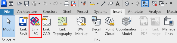
<div align="left"><figure><img src="https://files.gitbook.com/v0/b/gitbook-x-prod.appspot.com/o/spaces%2FprbMwk21uTZaZrhwExiJ%2Fuploads%2FCcsAizR01AtlBhLe1CSu%2FRevit-link-ifc.png?alt=media&#x26;token=42a74762-515b-4e49-a87f-5133811369a8" alt=""><figcaption><p><em>Link IFC</em> can be found in the <em>Insert</em> tab</p></figcaption></figure></div>

Linking or referencing IFC files in Revit is the recommended and most reliable method for using IFC data in Revit. This method processes the IFC file in the background and displays it as a reference. If the linked IFC file is updated, it will be reloaded and updated in Revit the next time the project is opened. Alternatively, it can be updated manually by selecting it in the project browser and clicking *Reload.*

## New in Revit 2026: Positioning options when linking IFC files

<div align="left"><figure><img src="/files/1UWIQ1y9J62o8ACZhqQG" alt=""><figcaption></figcaption></figure></div>

{% hint style="danger" %}
Prior to Revit 2026, selecting the insertion point when linking an IFC in Revit is not possible. This means that an IFC will always be linked ORIGIN to ORIGIN in Revit:

<mark style="color:red;">**IFC Origin**</mark> <mark style="color:red;"></mark><mark style="color:red;">selected during the export will be positioned to match the</mark> <mark style="color:red;"></mark><mark style="color:red;">**Revit Internal**</mark> <mark style="color:red;"></mark><mark style="color:red;">Origin.</mark>

As Revit Internal cannot be moved, the following workflows are recommended:&#x20;

* Ideally, place the project base point in all software solutions to match the Revit internal origin in relation to the project.&#x20;
* If the above is not possible:  Use a coordination marker (e.g. a cube or a pyramid) at the project base point and manually align the linked model in Revit. <br>

Linking absolutely geo-referenced files in Revit might lead to issues, as the geometry is very far from the Revit origin. Check [this article ](/revit/ifc-export-settings-dialog/geographic-reference)for more information. \
As a last option, try [**opening**](/revit/using-ifc-files-in-revit/open-ifc) a geo-referenced IFC file in Revit and then linking the .RVT in the main project.&#x20;
{% endhint %}

Linking IFC files in Revit creates three files in the same directory:<br>

<figure><img src="https://files.gitbook.com/v0/b/gitbook-x-prod.appspot.com/o/spaces%2FprbMwk21uTZaZrhwExiJ%2Fuploads%2F3Eih21nHqKVA65DqdX6S%2Fimage.png?alt=media&#x26;token=d58c95fe-307f-4cce-bce0-ff8b6dd25c1e" alt=""><figcaption></figcaption></figure>

\*  **ifc.RVT** is used by Revit internally and must not be moved or edited to maintain the relationship between the Revit project and the IFC file.&#x20;

\*  **ifc.log.html** is a logfile created during the conversion process. It contains a report about the linked elements, error messages, and hints that can help troubleshoot.&#x20;

\*  **ifc.sharedparameters.txt** contains the shared IFC parameters found in the IFC. To schedule parameters from the linked IFC file in the main project, these must be added to the main project.

<figure><img src="/files/B8XHOZI0tEgJEkMIUYNW" alt=""><figcaption><p>Use the <em>Shared Parameters</em> Dialog from the Manage tab<br>to add parameters from <em>ifc.sharedparameters.txt</em> to the current project</p></figcaption></figure>

💡 Some best practices for using shared parameters from linked IFC flies can be found in this article: <https://bim-me-up.com/en/ifc-vorlage-in-revit-fur-intelligente-informationsverwaltung/>&#x20;


# Open IFC

<div align="left"><figure><img src="/files/v25QP5aBmuku69vU4p0C" alt=""><figcaption></figcaption></figure></div>

IFC files can be opened in Revit, which converts IFC elements to editable native Revit geometry.&#x20;

It's essential to keep in mind that IFC is designed mainly for coordination purposes and has limited functionality when it comes to converting and editing in proprietary software solutions. However, buildingSMART is working on this issue with newer concepts, such as the IFC4 Design Transfer View, which is currently in development.

In addition, modifying IFC data can result in legal issues, as it may alter the official deliverable.

If editing IFC data in an authoring tool such as Revit is necessary, it must be considered that this process might lead to a data loss. Therefore, the imported model should be checked for errors or missing elements.&#x20;

Following best practices can help when importing IFC files in Revit:

\-  Using an [IFC viewer](/understanding-ifc/ifc-viewers) to check whether the elements are classified correctly – if this is not the case, a new IFC file with a correct classification should be requested.

\-  Checking the header for information about the IFC schema and MVD in a text editor. IFC2x3 Coordination View 2.0 is currently recommended for best results when *opened* in Revit.

\-  Excluding all IFC classes not required in Revit by inserting *DontImport* in the mapping table found in [IFC Options](broken://spaces/sLn8fNau3bs32lO49dL5).&#x20;

\-  Disabling *AutoJoin Elements* and C*orrect lines that are slightly off-axis in the Open Dialog* to speed up the import process.


# IFC Export - Category Mapping

The most important export setting is the mapping of Revit categories to IFC classes using the Category Mapping, which was significantly improved with Revit 2025 and integrated in the IFC Export settings found under *File -> Export -> IFC:*&#x20;

<figure><img src="/files/l1cnqXcZOZnQBSCH1Z5c" alt=""><figcaption></figcaption></figure>

The Category Mapping dialog allows the creation of multiple mapping templates and their export and import for use in different projects.&#x20;

The mapping itself is accomplished using a predefined list that allows the selection of IFC Classes and correspondent types:&#x20;

<figure><img src="/files/Nm08aFRGKctPXUMeOb2H" alt=""><figcaption></figcaption></figure>

* ![](https://help.autodesk.com/cloudhelp/2025/ENU/Revit-DocumentPresent/images/GUID-B4FAB156-A881-4C0E-A305-AB53E5929732.png) Select to include the category in the IFC export, or clear to exclude it from the export. Use the arrow control to expand or collapse the view of sub-categories. The control at the top of the column will select or clear all category selections.
* ![](https://help.autodesk.com/cloudhelp/2025/ENU/Revit-DocumentPresent/images/GUID-D38A982B-8B41-4D84-BAF4-E6582FB60483.png) Use the dialog launcher to open the IFC Entity Selection dialog. Set the Predefined Type to USERDEFINED to enable the user-defined type column.
* ![](https://help.autodesk.com/cloudhelp/2025/ENU/Revit-DocumentPresent/images/GUID-229565AE-E0B7-4BFC-A584-AD3A9558441E.png) - Use the reset control to reset the IFC Class and Predefined Type to default values. Use the control at the top of the column to reset all values to the default.
* ![](https://help.autodesk.com/cloudhelp/2025/ENU/Revit-DocumentPresent/images/GUID-0ABF283D-6207-412A-A81C-644D1B4AF850.png) - Use the search bar to filter the category list.

### Category Mapping in Revit 2024 and older

&#x20;Find the *Export mapping table by navigating to* *File -> Export -> Options -> IFC Options:*

<figure><img src="/files/MOIysmPhKAbrZ6s8R7AX" alt=""><figcaption></figcaption></figure>

This Export table requires a manual entry of the IFC class and type. More information can be found in this article: [Supported IFC Class mapping when exporting Revit models to IFC](https://knowledge.autodesk.com/support/revit/learn-explore/caas/sfdcarticles/sfdcarticles/Supported-IFC-Class-mapping-when-exporting-Revit-models-to-IFC.html?collection=181476)

💡 Does your IFC Export result in an empty IFC file? (Prior Revit 2025)

When using Revit in different languages, the “exportlayers-ifc-IAI.txt” will be generated according to the first language in which the dialog is launched. To reset the mapping table to the default settings and/or current language, delete the text file (path indicated in the header) and click “Standard” in the dialog above – this will recreate the mapping file with the hardcoded settings. This has been resolved in Revit 2025.&#x20;

{% hint style="info" %}
Note: Mapping Revit Subcategories as well as the IFC types is limited at this level – only the main Revit categories should be mapped to IFC classes. For more granular mapping, the elements can be mapped individually.&#x20;

Replacing the IFC Class Name with *Not Exported* will completely exclude the Revit category from export.
{% endhint %}


# Basic IFC Structure

The structure of the IFC schema is complex and contains many abstract layers that are not visible to the end user. For building projects, the structure visible in IFC viewers typically looks like this:&#x20;

<figure><img src="/files/oyNQbTvyBmVp2Us2oJcg" alt=""><figcaption><p><em>Note that the new developments in IFC4 include infrastructure classes, which can be visible instead of IfcBuilding</em></p></figcaption></figure>

The top 3 entities (IfcProject, IfcSite, and IfcBuilding) are containers carrying relevant information about the project and the setting.&#x20;

### [IfcProject](https://standards.buildingsmart.org/MVD/RELEASE/IFC4/ADD2_TC1/RV1_2/HTML/schema/ifckernel/lexical/ifcproject.htm)

The top-level entity is typically the main container in the tree structure as seen in IFC viewers. It doesn’t have any standard Psets defined in the schema.&#x20;

Following Revit project properties will be automatically attached to the IfcProject if populated, and it is also possible to attach [custom (user-defined) properties](/revit/ifc-export-settings-dialog/property-sets/user-defined-properties):&#x20;

<figure><img src="/files/uUJkv0S7b02HAhO9wDwL" alt=""><figcaption></figcaption></figure>

{% hint style="info" %}
Note: The parameters grouped under *IFC Parameters* have been added manually and assigned as Instance parameters to the category Project Information. (More information: [Using IFC Shared Parameters](/revit/ifc-export-category-mapping/using-ifc-shared-parameters))

Layer name / Color is only relevant for entities that represent physical objects, while IfcProject is a container and therefore has no physical representation in CAD software.&#x20;
{% endhint %}

### [IfcSite](https://standards.buildingsmart.org/MVD/RELEASE/IFC4/ADD2_TC1/RV1_2/HTML/)

The second level represents the Site and is a bit more complex than the project, as it can also be associated with a topography object in Revit. In a scenario *without topography*, the main properties can be added to *Project Information* in Revit, using the [shared parameter file](/revit/ifc-export-category-mapping/using-ifc-shared-parameters) provided with Revit IFC:

<figure><img src="/files/nVoNGPGJHJ7Ms9Hha6Im" alt=""><figcaption></figcaption></figure>

The RefLatitude and RefLongitude are derived from the *Location* set in the *Manage* tab in Revit.

If the project contains a Topography object, the IFC properties can also be assigned on this level and will override the previously shown properties specified in *Project Information*.

<figure><img src="/files/AUMlKMjKG0hyt8wwsP99" alt=""><figcaption></figcaption></figure>

This can be repeated with the other properties available, like LongName.

According to the [IFC4 RV documentation](https://standards.buildingsmart.org/MVD/RELEASE/IFC4/ADD2_TC1/RV1_2/HTML/link/ifcsite.htm), IfcSite has two predefined Psets: Pset\_SiteCommon and Pset\_LandRegistration. These are both supported and included in the shared parameters file. If added to Revit (either to the Project Information or to the Topography Category) and populated, they will be exported and attached to IfcSite.&#x20;

### [IfcBuilding](https://standards.buildingsmart.org/MVD/RELEASE/IFC4/ADD2_TC1/RV1_2/HTML/)

The third container is also the first spatial container and represents the building. Its properties are again defined using the Revit *project information*. Additional supported properties can be added from the [IFC Shared Parameters file](/revit/ifc-export-category-mapping/using-ifc-shared-parameters) and attached to the Project Information Category in Revit:&#x20;

<figure><img src="/files/LRyMWDHSHrtQ280Ck4Ai" alt=""><figcaption></figcaption></figure>

<figure><img src="/files/IbkuAQTLXDmrh9OFmdYu" alt=""><figcaption></figcaption></figure>

As long as the properties are populated, the PSets defined in the IFC schema will also be automatically exported.&#x20;

{% hint style="info" %}
The IFC schema itself supports multiple buildings; however, due to its internal structure, Revit exports only one building per project.
{% endhint %}

### [IfcBuildingStorey](https://standards.buildingsmart.org/MVD/RELEASE/IFC4/ADD2_TC1/RV1_2/HTML/schema/ifcproductextension/lexical/ifcbuildingstorey.htm)

The fourth container is equivalent to building stories and hosts the building elements, like Walls or Furniture. Since Revit often has many reference levels that do not represent the building structure, every Revit level has the property **Building Story,** which defines whether the level will be exported to IFC.

If this option is checked, the level will be exported to IFC; if not, it will be ignored. The elements that are assigned to a non-building story in Revit will be automatically assigned to the next lower building story. If there is no lower building story, they are assigned to the next *upper*. Every project should have at least one Building Story.

<figure><img src="/files/cJvBy2rPABeE2g9hbVCT" alt=""><figcaption></figcaption></figure>

The following videos provide an overview of the topics discussed in this section: \ <mark style="background-color:orange;">▶️</mark> [<mark style="background-color:orange;">IfcProject, IfcSite, IfcBuilding - default properties and naming</mark>](https://www.youtube.com/watch?v=1DVluDqkjPA)\ <mark style="background-color:orange;">▶️</mark>[<mark style="background-color:orange;">Revit Levels in IFC</mark>](https://www.youtube.com/watch?v=npt2a9zCJZI)


# Category Mapping override

There are many cases where the [global mapping discussed previously ](/revit/ifc-export-category-mapping)needs to be overridden for specific elements. The reason behind this is that the IFC classes are often more granular than Revit categories and also have their predefined types based on their use.

This functionality has been improved since **Revit 2023** and now offers a selection box for easier assignment of IFC classes and types:&#x20;

<figure><img src="/files/WTHLdyYDAKIquTGUjyCT" alt=""><figcaption><p>Element-based IFC Mapping in Revit 2023 and newer - Notice that the same parameters exist both at the instance and type level to cover multiple use cases. If both values are set, the instance value will override the type value.</p></figcaption></figure>

**Revit 2022 and earlier** is still using the IFC Class and Type manual assignment to the parameter *IfcExportAs*. If it does not already exist in the project, it is strongly recommended to add this parameter as a shared parameter using the [shared parameter files](/revit/ifc-export-category-mapping/using-ifc-shared-parameters) included with Revit IFC:

<figure><img src="/files/poqxVxlLi7WUuGJMJYVI" alt=""><figcaption><p>In Revit 2022 the IfcExportAs parameter needs to be added to the project and filled manually using valid values for IFC Class / type.<br>This parameter can also exist both on Instance and type level to cover multiple cases (instance value overrides the type). </p></figcaption></figure>

The value of this parameter needs to be *IfcClass.TYPE* – both of these are defined in the IFC schema. Like the main mapping table, *Don‘t export* can exclude a particular element from export.

It is also possible to map Revit categories to other classes, however Revit will not be able to add missing properties and relationships. In the following example, a wall is mapped to IfcRailing with the predefined type BALUSTRADE:

<figure><img src="/files/1KiyRXCaLrTAxEZo2vao" alt=""><figcaption></figcaption></figure>

However, if compared to a regular railing, not all custom properties defined in the IFC Schema can be automatically mapped and have to be assigned manually:&#x20;

<figure><img src="/files/YGEpZlR62scfECBr11CT" alt=""><figcaption></figcaption></figure>

{% hint style="info" %}
Note: There are some restrictions to the mapping of more complex system families, such as curtain walls, to other IFC classes. A current overview of the supported IFC Class mapping when exporting Revit models to IFC can be found in this [AKN article](https://www.autodesk.com/support/technical/article/caas/sfdcarticles/sfdcarticles/Supported-IFC-Class-mapping-when-exporting-Revit-models-to-IFC.html?collection=181476).&#x20;
{% endhint %}

The IFC Schema allows USERDEFINED types. The correct use of these is achieved by adding USERDEFINED as *value* for the actual *IfcType* and specifying the actual user-defined type name in *IfcObjectType*.&#x20;

\
Example:&#x20;

Overview of available types defined for IfcRailing in the IFC 4 documentation:

<table><thead><tr><th width="206.5">Constant</th><th>Description</th></tr></thead><tbody><tr><td>HANDRAIL</td><td>A type of railing designed to serve as an optional structural support for loads applied by human occupants (at hand height). Generally located adjacent to ramps and stairs. Generally floor or wall mounted</td></tr><tr><td>GUARDRAIL</td><td>A type of railing designed to guard human occupants from falling off a stair, ramp or landing where there is a vertical drop at the edge of such floors/landings.</td></tr><tr><td>BALUSTRADE</td><td>Similar to the definitions of a guardrail except the location is at the edge of a floor, rather then a stair or ramp. Ex- amples are balustrates at roof-tops or balconies.</td></tr><tr><td>USERDEFINED</td><td>User-defined railing element, a term to identify the user type is given by the attribute IfcRailing.ObjectType.</td></tr><tr><td>NOTDEFINED</td><td>Undefined railing element, no type information available.</td></tr></tbody></table>

&#x20;Userdefined type definition in Revit:

<figure><img src="/files/U2ALRk904myks90LpBkk" alt=""><figcaption></figcaption></figure>

It is also possible to specify a *userdefined* IfcName during export using the type parameter *NameOverride* for the type name as well as the instance parameter *IfcName* to comply with specific naming conventions:&#x20;

<figure><img src="/files/VkUT8HgFevXttxJfk1HY" alt=""><figcaption></figcaption></figure>


# Excluding specific elements

In certain situations, it might be necessary to exclude certain elements from the IFC Export. This can be achieved in two ways:&#x20;

1. &#x20;Hiding specific elements in the Revit view and exporting visible elements only:

<figure><img src="/files/DI7q8lj1kWFDr6tZFSoj" alt=""><figcaption></figcaption></figure>

2. Excluding elements from export using specific parameters:&#x20;

Revit 2023 and newer:&#x20;

<figure><img src="/files/9Al1TyTFMMgrXtj1mqxQ" alt=""><figcaption><p>Notice that the same parameters exist both at instance and type level to cover multiple use cases. <br>If both values are set, <strong>the instance value will override the type value</strong></p></figcaption></figure>

In Revit 2022 or older, setting the value for *IfcExportAs* to *Not Exported* will lead to the same result.&#x20;


# Export for Layer-based Software

Some software products may require a layer structure to be added to the IFC classification. Revit automatically assigns the layer value according to the default CAD (.dwg/.dgn) mapping file. The default configuration file is: C:\ProgramData\Autodesk\ RVT 20xx\exportlayers-dwg-AIA.txt

The configuration found in this file can be adapted from the Revit UI when selecting Export > Options > Export settings DWG/DXF or manually using the syntax:

\<Revit Category Name>\<tab>\<tab>\<Layer Name>

<figure><img src="/files/gQpurGZm5PVPAvKp5ns7" alt=""><figcaption></figcaption></figure>

The reference to a custom layer reference file needs to be added to the Revit.ini file which can be found in the following location: C:\Users\\\<USER>\AppData\Roaming\ Autodesk\Revit\Autodesk Revit 20xx

The full path to the layer reference file is added in the line starting with ExportLayersNameDGN=

For Example: ExportLayersNameDGN=C:\Users\\\<USER>\Documents\RevitLayers.txt Just like with the class mapping, sometimes it is needed to assign the layer value on the element level. For this, you can use the shared parameter *IfcPresentationLayer,* which is of course included in the official shared parameter files.


# Using IFC Shared Parameters

Not all properties defined in the IFC schema are part of Revit by default, as this would overload the database. It is recommended to add only the parameters needed in a specific project. Frequently used parameters can be added to the project templates.

These can be added to the Revit Project using the Autodesk Parameter Service, which is available since Revit 2023 and automatically retrieves shared parameters through Autodesk Docs:&#x20;

<figure><img src="/files/zGCIvgwZH55yKfUsKdJM" alt=""><figcaption><p>The Parameter Service offers several benefits, such as easy access and the possibility to preset categories and parameter types. </p></figcaption></figure>

Alternatively, the IFC shared parameters can also be added using the traditional shared parameters stored in text files. Revit IFC Open Source extension ships with two shared parameter files which are stored in the following folder after the installation

C:\ProgramData\Autodesk\ApplicationPlugins\IFC \<Version>.bundle\Contents\\

They can also be downloaded from the [GitHub repository](https://github.com/Autodesk/revit-ifc/tree/master/Install/Program%20Files%20to%20Install).

The two files are:

\-  IFC Shared Parameters-RevitIFCBuiltIn\_ALL.txt

\-  IFC Shared Parameters-RevitIFCBuiltIn-Type\_ALL.txt

The shared parameters are added to Revit using the Dialog found in *Manage > Project Parameters* and it is recommended to use the first file for adding the Instance parameters and the second one for Type parameters.

<figure><img src="/files/Sfvl9Dqyh0QyaXPq2yWc" alt=""><figcaption></figcaption></figure>

The reason for having two files is that the IFC schema is based on types and instances, just like Revit. In IFC, however, the same parameter can be attached to instances and types (and can also be given different values), while Revit requires the user to choose between type and instance when assigning a parameter – it is not possible to select both.

Depending on the project requirements, it might be necessary to attach certain properties to both IFC Instance and IFC Type levels. To achieve this, the instance properties from the first file and the type properties from the second can be added. The properties from the second file will display *\[Type]* in the name in Revit, which will however be removed during export.

To illustrate this, let’s assume you need to deliver your doors with the Pset\_ DoorCommon containing different FireRating on Type and Instance. Steps necessary:

\-  Add the Instance property according to the previous screenshot from *IFC Shared Parameters-RevitIFCBuiltIn\_ALL.txt,* assign it to the Door Category, and ideally group it under IFC Parameters (not obligatory but improves the overview).

\-  Add the Type property from *IFC Shared Parameters-RevitIFCBuiltIn-Type\_ALL.txt* and assign it to the Type this time, select the Door Category, and group it under IFC Parameters.

&#x20;

The result should look like this:

<figure><img src="/files/LXa5cOiLAZgizpU6VRxC" alt=""><figcaption></figcaption></figure>


# IFC Export Settings Dialog

The IFC export dialog in Revit is located under *File > Export > IFC,* and it offers the direct selection of all built-in Model View Definitions (MVD).&#x20;

This dialog also allows the export of all open projects, not only the active one, using the same settings:

<figure><img src="/files/Z8zrYEZ86jLpmWPYDjcO" alt=""><figcaption></figcaption></figure>

The selection of the IFC version and MVD is crucial for the quality of the content exported to IFC.\
The most commonly used MVDs are IFC2x3 Coordination View 2.0 and IFC4 Reference View.

In addition, these settings can be further modified by selecting Modify setup. The following pages provide detailed documentation about these settings.


# General Settings

By selecting *Modify Setup,* the settings for the In-Session Setup can be altered, or a new Setup can be created.&#x20;

NOTE: It is not possible to edit the predefined setups in <> brackets!

<figure><img src="/files/xQP1SN3RPKBn6gtjmuux" alt=""><figcaption><p>General Settings in the <em>Modify Setup</em> Dialog</p></figcaption></figure>

**IFC Version** \
allows the selection of the IFC version and MVD, typically IFC2x3 Coordination View 2.0 or IFC4 Reference View. For a better understanding of the IFC Version and MVD, check the first chapter of this manual.

**Exchange requirement** \
is only valid when using IFC4, as buildingSMART has defined different use cases for the certification of Architectural, Structural, and MEP exchange. However, the resulting differences in the exported IFC are minor and negligible for most end users. *Structure* or *MEP* is recommended for any trade-specific use cases and calculations. For general data exchange, please use *Architectural.*

**Category Mapping (New since Revit 2025)** \
For more information, please [check this section.](/revit/ifc-export-category-mapping/category-mapping-override)

**File Type** \
allows the selection of alternative types such as IFCXML or the zipped versions of IFC / IFCXML. For most use cases, the default setting IFC should be your first choice.

**Phase to export** \
allows the selection of a specific phase in the project to be exported. The *default* phase to export is the *last phase* in the project. If „Export only elements visible in view“ (available in [Additional Content](/revit/ifc-export-settings-dialog/additional-content)) is selected, the phase of the current view will be used, and this option will be greyed out.\
When exporting Phases, only *existing* elements will be exported - if an element is shown as demolished in the phase selected for export, the element won't be exported to IFC. \
This won't apply for Revit Links, resulting in demolished elements from a linked file being exported.&#x20;

**Space boundaries** \
defines the level of room/space boundaries exported:

\- None - room/space boundaries are not exported.

\- 1st level - the room/space boundaries are included but are not optimized to split elements with respect to spaces on the opposite side of the boundary.

\- 2nd level - the room/space boundaries are included and are split with respect to spaces on the opposite side of the boundary. A second-level space boundary considers the material of the building element and the adjacent spaces behind it, providing thermal properties for further analysis.

The information is attached to spaces as well as to room boundary objects like walls and can be viewed by most viewers (example FZK viewer, left Level None, right 1st Level):

<figure><img src="/files/1PSMGktwuBVD6K1yKiZg" alt=""><figcaption></figcaption></figure>

**Split Walls, Columns, Ducts by level** \
splits all elements crossing multiple building stories automatically when exporting. When using this option, it is important to check levels defined as *Building Story* and also review the option *Level Above. .Default* will use the next higher Building Storey to cut all elements assigned to the current level, unless another level is selected explicitly. The elements created by splitting will be assigned to the levels they were cut by.

<figure><img src="/files/bYC8ANjfyx39sN2hEAIC" alt=""><figcaption></figcaption></figure>

**File Header Information** allows the definition of Author’s name, E-Mail, Organization and Authorization in the file IFC header.

**Project Address** overwrites the address set in the project information either for building and/or site when exporting and also pushes this information back to Revit if *Update Project information* is selected.


# Additional content

<figure><img src="/files/1kAZRd30yTjH1G8yuioW" alt=""><figcaption></figcaption></figure>

**Linked Files:** allows a separate or federated (since Revit 2024) export of Revit models linked in the project file. \
When exported everything in one consolidated file, it is possible to select whether to export in same IfcProject or same IfcSite. The second option will use the IfcSite defined in the host project:&#x20;

<figure><img src="/files/JdTXtrW0LVMiiYOIqXYZ" alt=""><figcaption></figcaption></figure>

**Export only elements visible in view** will use the currently active view to evaluate which elements to export. As 3D views in Revit do not show rooms, areas, and spaces, it is possible to include these using the second option, Export rooms, areas, and spaces in 3D views.

**Include Steel Elements** exports structural steel, including the steel connections created in Revit.&#x20;

**Export 2D plan view elements** will include 2D elements supported by the IFC schema, such as notes and filled regions. Grids are considered 3D elements and can be exported by assigning the Grids Revit Category to the *IfcGrid* class. It should be noted that IFC is a 3D-oriented schema and only a limited number of 2D elements are supported in general, therefore PDF is still commonly used for 2D documentation.


# Property Sets

The property sets contain the information defined in the model and are therefore the most important export setting besides the classification.&#x20;

{% hint style="info" %}
Revit won't export *empty properties (properties with no value assigned).*&#x20;
{% endhint %}

<figure><img src="/files/Q0HQryZX2BR2eQqlkuWc" alt=""><figcaption></figcaption></figure>


# Revit Property Sets

**Export Revit property sets** is deactivated by default, as this option will export all Revit properties according to their internal grouping. This will include a lot of obsolete information in the IFC and will also significantly increase the file size. It is recommended to use this option with caution and for testing purposes only.


# Common Property Sets

**Export IFC common property sets** exports the default properties defined in the IFC schema and is activated by default. Existing Revit properties are automatically mapped to the IFC properties.

The common property sets can be recognized by the Pset\_ prefix after the export:

<figure><img src="/files/YlVMrdjH7blCrFbo5Goe" alt=""><figcaption></figcaption></figure>

As the IFC schema contains many properties which are not commonly used in all projects and therefore not included in Revit by default, only a subset of the properties defined in a Pset will be exported using this option. The complete Pset\_ WallCommon includes several properties not existing in Revit by default:

<table><thead><tr><th>Property</th><th>Description</th><th data-hidden></th></tr></thead><tbody><tr><td>Reference</td><td>Component type (type name)</td><td></td></tr><tr><td>AcousticRating</td><td>Sound insulation clalss</td><td></td></tr><tr><td>FireRatingCombustible</td><td>Fire-resistance class (type parameter)</td><td></td></tr><tr><td>SurfaceSpreadOfFlame</td><td>Fire behavior</td><td></td></tr><tr><td>ThermalTransmittance</td><td>U-value (type parameter)</td><td></td></tr><tr><td>IsExternal</td><td>Exterior component (type parameter, given as yes/no)</td><td></td></tr><tr><td>ExtendToStructure</td><td>Fixed on top (behavior)</td><td></td></tr><tr><td>LoadBearing</td><td>Load bearing (instance parameter)</td><td></td></tr><tr><td>Compartmentation</td><td>Fire compartment-defining component</td><td></td></tr></tbody></table>

There are several options to add these properties. The first and the most simple one is by adding the properties with the same name and data type as defined in the IFC schema to Revit. The easiest way to accomplish this is by using the IFC shared parameters file already introduced in this manual (see: Using IFC Shared Parameters). This will make sure that the spelling and the data type are correct. Once these properties have been added and populated, they will be automatically added to the Pset upon export:

<figure><img src="/files/paVzvaQpxefhoHJYAfOz" alt=""><figcaption></figcaption></figure>

Alternatively, it is possible to [map other properties](/revit/ifc-export-settings-dialog/property-sets/parameter-mapping-table) (as long as they have the same data type) to the corresponding IFC properties.

Following video provides an overview of the topics discussed in this section: \ <mark style="background-color:orange;">▶️</mark> [<mark style="background-color:orange;">Exporting IFC Common Property Sets from Revit</mark> ](https://youtu.be/5q6Egq9tthE?si=V1ZfyQMh4tpgY9CF)


# Base Quantities

**Export base quantities** will include another type of property sets defined in the IFC schema as well, which are meant specifically for estimation and QTO purposes.

For a wall these quantities typically look like this:<br>

<figure><img src="/files/3pc2vCdeyWIbkmHtCIoX" alt=""><figcaption></figcaption></figure>

&#x20;  &#x20;


# User Defined Properties

Besides the Common Property Sets defined in the IFC Schema, it is also possible to define custom property sets and Revit offers two ways to do this: using schedules or a configuration file.&#x20;

Note: only the official property sets defined in the IFC schema are allowed to start with “Pset\_ “

The following video provides an of the topics discussed in this section:\ <mark style="background-color:orange;">▶️</mark> [<mark style="background-color:orange;">Export any Revit Property to IFC using Custom Property Sets</mark> ](https://youtu.be/SswHKtcM3mI?si=lFgb2niTXjn_f8AV)


# Schedules

**Export schedules as property sets** allows the creation of user-defined property sets through Revit schedules. All properties which are not part of the standard property sets defined in the IFC schema can be added to custom property sets. As Revit pro- jects can have many schedules, it is also possible to limit this option to Schedules containing IFC, Pset, or Common in the title.

All properties are collected in the schedule and can be found in the IFC upon export:

<figure><img src="/files/RjaOizWseF9HEw4HnRiZ" alt=""><figcaption></figcaption></figure>

The advantage of this workflow is that it is not necessary to worry about data types or configuration files, however, the schedules are not that easily transferrable between projects, which is why there is also a second option to create user-defined property sets.


# Configuration File

**Export user-defined property sets** is the equivalent to exporting schedules as property sets, however, it uses a text file as a configuration file instead. The default template file can be found here: C:\ProgramData\Autodesk\ApplicationPlugins\IFC 20xx.bundle\Contents\20xx and includes detailed instructions and examples.

<figure><img src="/files/s0QgH1ljJ74qTnqP4J0l" alt=""><figcaption></figcaption></figure>

Everything between <> is replaced:

**\<Pset Name>:** Name of the Pset, don’t use Pset\_ as Prefix as this is reserved for standard IFC Psets

**I\[nstance]/T\[ype]:** used to specify Instance or Type properties, obsolete in current versions as the selection happens automatically, use either I or T&#x20;

**\<element list separated by ‘,’>**: this is the place where either one or more IFC classes for which this Pset will be applied are listed, e.g. IfcWall, IfcSlab, IfcColumn. If the Pset should be applied to all elements, use the next higher entity ( with - IfcBuildingElement building elements like walls, doors, etc. or IfcElement to include also Civil and Distribution elements. This can be checked in the IFC documentation by searching for Entity inheritance.

<mark style="background-color:orange;">Note:</mark> <mark style="background-color:orange;"></mark><mark style="background-color:orange;">**Starting with Revit 2024.1, it is no longer sufficient to specify the IFC class such as IfcElement or IfcWall to export Type Properties , but rather requires the specification of the type (e.g. IfcElementType or IfcWallType).**</mark> \ <mark style="background-color:orange;">**As there is no type definition for doors and windows in IFC 2x3 schema,  IfcDoorStyle and IfcWindowStyle need to be used. When exporting to IFC4, IfcDoorType / ifcWindowType are used.**</mark>

**\<Property Name>:** property name as displayed in Revit

**\<Data type>:** the supported IFC data types are listed in the template file, the most commonly used are Text, Integer, Real, Length, Volume, Boolean.

There are currently 40 IFC property types that are supported in the Revit IFC export. Not every property type in Revit can be mapped directly to the IFC type, as IFC uses a different way of specifying some of the units. When mapping Revit data type that does not have a direct mapping to the IFC data type, it can be mapped to a primitive type, e.g. Real or Integer. This will export the value unconverted using Revit internal units.

<figure><img src="/files/yNenJTEQQooLeUkm9Ns0" alt=""><figcaption></figcaption></figure>

<\[opt] Revit parameter name, if different from IFC> is an optional field and can be omitted, if the name of the Revit property should also be used for the IFC property. If the IFC property should have a different name, it can be entered here.

{% hint style="info" %}
Note: All entries are separated by a \<TAB> and the file should be saved in the UTF-8 format.
{% endhint %}

Example:

<figure><img src="/files/l9GMeNj62s8QoMnwXZxg" alt=""><figcaption></figcaption></figure>


# Parameter mapping table

**Export parameter mapping table** allows the mapping of custom Revit properties to the common IFC properties, as long as they have the same data type. Similarly to the user defined property sets, this is accomplished with a text based mapping file. There is no default template included for this file, however the syntax is fairly simple:

IFC Common PropertySet Name \<TAB> IFC Property Name \<TAB> Revit Property Name

By using this method, Revit properties can be named according to the project or company standards and will be mapped according to the correct IFC terminology upon export.

<figure><img src="/files/EHwRA8DSijuz9CxfJnXL" alt=""><figcaption></figcaption></figure>

&#x20;  &#x20;


# Level of Detail / Advanced

### Level of Detail

This option lets you select the level of detail for tessellated geometry. By default, the level of detail is set to “Low”. As the Level of detail has impact on file-size and data-quality it is recommended to evaluate this option before export.

These options allow you to control the level of tessellation for some Revit elements. Selecting Medium or High for this option generally results in larger, but more accurate, BRep and profile representations.

The main Revit elements affected by this control are: elbows, floors, pipe fittings, railings, ramps, spaces, and stairs. Highly-detailed extrusion profiles are also affected for these items.

<figure><img src="/files/8F4BMh3ZqlgPhKefPdMc" alt=""><figcaption></figcaption></figure>

### Advanced

This tab offers advanced options which can be used in case of specific requirements:&#x20;

<figure><img src="/files/dqaplIJnZCogkzUQZjrw" alt=""><figcaption></figcaption></figure>

**Export parts as building elements** is only relevant when exporting for systems which don't support IfcBuildingElementPart, as it will export parts as building elements instead.&#x20;

**Allow use of mixed “Solid Model” representation** enables the export of combined swept solid and B-rep models. A geometric object in an IFC data model is normally generated from either one or several swept solid objects, or from B-rep objects alone. The combination of these two types of representation is not enabled by default in the IFC schema. For more complex components, in particular, this leads either to a larger file size or incorrect presentation, as elements are wholly represented B-rep objects. Solid model representation combines the two types of representation within a single class, which can mean better geometric results at a smaller file size for complex models. It should be noted, however, that the IFC file exported using this setting no longer complies with the default IFC schema and must therefore be accepted as such by all those involved in the project. For certain areas of use, it may be necessary to have an unaltered default schema for export.

**Use active view when creating geometry** will use the level of detail level of the current view (Coarse / Medium / Fine) and will export all objects according to the way they are displayed in Revit.

**Use family and type name for reference** will influence the way the naming of the reference in IFC. By default, the Revit Type name is used for the IFC reference. By activating this option, the family name will be used along with the type name:

<figure><img src="/files/1YbGn6kkhZiPeRsKC9Uw" alt=""><figcaption></figcaption></figure>

**Use 2D room boundaries for room volume** simplifies the calculation of the room volume based on two-dimensional spatial boundaries. Using the default settings, the Revit room geometry is used to determine the volume in IFC.

**Include IFCSITE elevation in the site local placement origin**: Select this option to include the elevation from the Z offset of the IFCSITE local placement. Clear the option to exclude it.

**Store the IFC GUID in an element parameter after export**: Select this option to store the generated IFC GUIDs in the project file after export. This will add „IFC GUID“ parameters to elements and their types, and Project Information for Project, Site, and Building GUIDS.

**Export bounding box** allows the export of bounding box representations.

**Keep Tessellated Geometry as Triangulation**: Select this advanced option to use a triangulation method that is compatible with older IFC 4 Reference View viewers.

**Use Type name only for IfcType name** excludes the family name for the IFC type name:

<figure><img src="/files/6ZRMN8wQZawO3Jkaa7pN" alt=""><figcaption></figcaption></figure>

**Use visible Revit name as IFC entity name**: influences the generation of the element name in IFC:

<figure><img src="/files/ZNhUZw1bDA9guTbmqr0l" alt=""><figcaption></figcaption></figure>

**Entities to Export** will open an additional dialog where specific entities can be excluded from the export. This Setting will override the global [IFC Mapping override](/revit/ifc-export-category-mapping/category-mapping-override).&#x20;

<figure><img src="/files/ZC0K4JI4tWZhETJRql85" alt=""><figcaption></figcaption></figure>


# Geographic Reference

**Coordinate base** allows the selection between Shared Coordinates, Internal Origin, Project Base Point and Survey Point.

Every Revit project has initially three origins, which are usually hidden by default, but can be shown by going to Visibility Settings of your View > Site:

<figure><img src="/files/FCLs3iZvnOk7NLWifr9L" alt=""><figcaption></figcaption></figure>

\-  **Internal Origin** cannot be moved and also represents the center of the 20 mile region in which Revit tolerates Geometry. Any kind of Geometry created beyond this region will cause error messages and are to be avoided.

\-   **Project Base Point** defines the project coordinates and is usually placed at a grid intersection or a building corner on the ground level. Typically, all point coordinates and heights in the project will be referenced to this point. This point can be moved (manually or by typing in coordinates) to a desired position, but won’t move the project (unless the Project North, which is also visible in the Project Base Point, is changed). Prior to Revit 2020 the Project Base Point also had a clipped state, however, this has been removed. The Project Base Point from Revit 2020 on is always unclipped.

\-   **Survey Point** marks a relevant point in the real world and can be clipped on unclipped. Moving a clipped survey point will actually change the shared coordinate system of the model, while the unclipped survey point can be moved (either manually or by typing in coordinates) without any effect on the shared system, similar to the Project Base Point.

In the default templates all points should be located at the same spot and should be adjusted according to the project agreement.

Shared site is an additional concept used to set up the relation between linked models. One Revit project can contain multiple shared sites and this option will refer to the currently selected one:

<figure><img src="/files/UPmfmfRhnEQLcBF3dcAK" alt=""><figcaption></figcaption></figure>

More best practices are documented in this blog article and video: <https://bim-me-up.com/en/revit-ifc-und-koordinatensysteme/> \ <mark style="background-color:orange;">▶️</mark> [<mark style="background-color:orange;">Geo-referencing in Revit and IFC - The Basics</mark>](https://youtu.be/3WACsk_dKTE?si=nl0RGZVXoQOmDE5z)


# Classifications

### Classification Basics

Classifications group and classify BIM data simply and efficiently. In addition to the standard IFC classification according to the IFC classes, there are various classification systems available. The most commonly used are:&#x20;

1. MasterFormat | A master list for organizing construction work results, requirements, products, and activities. Mostly used in bidding and specifications, MasterFormat originated in North America and is produced by the Construction Specifications Institute (CSI) and Construction Specifications Canada (CSC).
2. UniFormat | For arranging construction information, organized around the physical parts of a facility known as functional elements, and mainly used for cost estimates. UniFormat originated in North America and is produced by the Construction Specifications Institute (CSI) and Construction Specifications Canada (CSC).
3. Uniclass | For all aspects of the design and construction process. In particular, for organizing library materials and structuring product literature and project information. Uniclass originated in the United Kingdom and is produced by the Construction Industry Project Information Committee (CPIC) and the National Building Specification (NBS).
4. OmniClass | For organization, sorting, and retrieval of product information for all objects in the built environment in the project lifecycle. OmniClass originated in North America and is produced by the Construction Specifications Institute (CSI) and Construction Specifications Canada (CSC).

More detailed information about the classification systems can be found in the Whitepaper available at [https://interoperability.autodesk.com](https://interoperability.autodesk.com/)

###

### UniFormat (Assembly Code)

The default classification system used in Revit is the Uniformat system. It is included as a text file with the Revit installation:&#x20;

C:\ProgramData\Autodesk\RVT  20XX\Libraries\\\<your  localization>\UniformatClassifications.txt

<figure><img src="/files/YIowD14RLUkwDHKwV7tt" alt=""><figcaption><p>Assembly Code Settings in Revit can be found under: Manage -> Additional Settings -> Assembly Code</p></figcaption></figure>

The UniFormat classification is assigned to the *Assembly Code* parameter and is automatically exported as [IFCClassification](https://standards.buildingsmart.org/IFC/RELEASE/IFC4_1/FINAL/HTML/schema/ifcexternalreferenceresource/lexical/ifcclassification.htm):

<figure><img src="/files/eifHBLSJUEG2saiaDIu0" alt=""><figcaption><p>Assembly Code assignment in Revit and export to IFC</p></figcaption></figure>

### Masterformat (Keynotes)

Keynotes in Revit are actually meant for annotating the Revit elements and are based on the MasterFormat by default and can be used for classification purposes as well. \
The classification (RevitKeynotes.txt) is included in the Revit library and can be found here:&#x20;

C:\ProgramData\Autodesk\RVT 20xx\Libraries\\\<your locale>

<figure><img src="/files/9SHgfdGwADIBDU7XEIW4" alt=""><figcaption><p>Keynote Settings can be found under: Annotate > Keynote > Keynoting Settings</p></figcaption></figure>

<figure><img src="/files/OyA1qXTdoBgdFvFVlvK0" alt=""><figcaption><p>Assigning Keynotes in Revit</p></figcaption></figure>

### OmniClass&#x20;

Omniclass is by the third classification system included in Revit by default, however it is only available for loadable families by default. For a full use of this classification, it is recommended to use the Standardized Data Tool for Revit.&#x20;

The classification file shipped with Revit can be found here:&#x20;

*C:\Users\\\<current username>\AppData\Roaming\Autodesk\Revit\\\<product name and release>*

For correctly exporting the Omniclass classification to IFC, it should be set manually under *Modify Setup -> Property Sets -> Classification Settings*:

<figure><img src="/files/p5YvFIFg1dvvpuHiZKeH" alt=""><figcaption></figcaption></figure>

###

###


# Multiple Classifications

Following shared parameters allow adding multiple classification systems during the IFC export.&#x20;

{% hint style="info" %}
The use of multiple classifications is restricted. IfcClassification attributes, including source, edition, edition date, name, description, location, and reference tokens are not supported and will be only available for the main classification.&#x20;
{% endhint %}

Shared parameters to be used for multiple classifications are:&#x20;

ClassificationCode

ClassificationCode(2)&#x20;

ClassificationCode(3)&#x20;

ClassificationCode(4)&#x20;

ClassificationCode(5)&#x20;

ClassificationCode(6)&#x20;

ClassificationCode(7)&#x20;

ClassificationCode(8)&#x20;

ClassificationCode(9)&#x20;

ClassificationCode(10)

{% hint style="info" %}
Note: ClassificationCode(1) does not exist.&#x20;
{% endhint %}

The syntax for specifying a classification is:&#x20;

**\[ClassificationName]Code:Title**

Example: \[Maturity]01:STATUS

<figure><img src="/files/F4G841CNxrybXh5ooAaR" alt=""><figcaption><p>Multiple Classifications in Revit</p></figcaption></figure>

<figure><img src="/files/KfMgp8UbXNwM3opqTCw3" alt=""><figcaption><p>Multiple Classifications in IFC</p></figcaption></figure>

&#x20; &#x20;


# Standardized Data Tool for Revit

The Standardized Data Tool for Revit (previously: Classification Manager for Revit) is a free tool developed by Autodesk that provides an easy way to manage and add classifications to Revit Model.&#x20;

It simplifies the process of assigning classification and offers fully customizable database systems to create custom classifications.&#x20;

<figure><img src="/files/LGS1yteMnKh0x0fIaJ99" alt=""><figcaption></figcaption></figure>

More information, documentation and video tutorials can be found here:  <https://interoperability.autodesk.com/standardizeddatatool.php>


# Advanced topics and Best Practices

This section is reserved for special topics and best practices for Revit users.&#x20;


# Zones

The export of IfcZones from Revit can be managed through shared parameters assigned to room objects.

The Revit parameter for zone classification is “ZoneClassificationCode”. The syntax is the same as for [multiple classifications](/revit/classifications/multiple-classifications):&#x20;

![](file:////Users/trishshurtz/Library/Group%20Containers/UBF8T346G9.Office/TemporaryItems/msohtmlclip/clip_image001.jpg)ZoneClassificationCode:                         \[ZoneClassificationName]Code:Title

<figure><img src="/files/PWFl1BajBLVe1IctBLH0" alt=""><figcaption><p>Zone-related parameters allow more detailed pieces of information on zones.</p></figcaption></figure>

*Room Name* and *ClassificationCode* are assigned to the rooms in IFC.

The *ZoneClassificationCode* is the classification parameter for zones.

*ZoneName, ZoneDescription* and *ZoneObjectType* define zones objects . \
&#x20;

<figure><img src="/files/Bz6ZAkO3PZcYb89LVpPP" alt=""><figcaption><p>Zones and properties in IFC viewed in BIM Vision</p></figcaption></figure>

<figure><img src="/files/0o8O8UqL7BkwaAiwhai3" alt=""><figcaption><p>IfcName  is mapped to Number, IfcDescription is mapped to IFCSpace – Description.</p></figcaption></figure>


# Assemblies

Assemblies are important for the higher-level grouping of components like structural beam systems, beam grids, and reinforcement cages. Unlike Revit groups, assemblies are exported to IFC as IfcElementAssembly with higher-level properties assigned.

To export assemblies, the IfcExportAs value is defined as *IFCElementAssembly:*

<figure><img src="/files/1YOTTqDYRQ9ibKEUqXR6" alt=""><figcaption></figcaption></figure>


# Nested Families

When exporting nested families, all elements will be assigned to one class / entity by default.

To export nested families as separate entities, they need to be set to *Shared* and can have an own IFC Class assigned, which can be different from the main family:&#x20;

### &#x20;&#x20;

<figure><img src="/files/JPJ2Q9f8late5weV56I2" alt=""><figcaption></figcaption></figure>


# Provision for Void

The use of proxy objects has largely been established in the preliminary design and coordination of cut openings in an integrated design process. In IFC those objects are called “provision for void” objects and are exchanged between domain models together with alphanumeric information and dimensions.

Proxy elements originate either from native Revit opening elements or are simple families with a void.

To export a provision for void object, the IfcExportAs needs to be set to *IFCElementProxy* and IfcObjectType to *PROVISIONFORVOID.*

<figure><img src="/files/J8DnAHTqrVPIowFlsWUX" alt=""><figcaption><p>IfcExportAs mapping in Revit 2024 and newer</p></figcaption></figure>

<figure><img src="/files/xXDFsYsIK7RPZScNZA2g" alt=""><figcaption><p>IfcExportAs mapping before Revit 2024 and result in IFC</p></figcaption></figure>


# Slabs and Floors

### Exporting Floors to IFC

Revit floors are often created using two separate elements: a load-bearing slab and the floor per room.

For IFC export all slabs are assigned to the *IfcSlab* class by default. The IFC classification however has a separate class for floors, which is called *IfcCovering*.&#x20;

To export the floor correctly, IfcExportAs is set to *IFCCovering* and IfcExportType *FLOORING*. Alternatively, both class and type can be assigned to IFCExportAs using the syntax: IFCCovering.FLOORING (or starting with Revit 2024 simply selected in the dialog):

<figure><img src="/files/bxoX3O7Zb2xLzVK5bu7a" alt=""><figcaption><p>IFC Entities and predefined Types for floors</p></figcaption></figure>

&#x20;

### Modeling Slabs for IFC Export

Even though Revit allows the creation of floor/sketched ceiling geometries from separate polygons, this should be avoided as it can lead to errors in calculations. When exported to IFC, such slabs are considered independent elements and all property values are assigned to each resulting IFC object.

<figure><img src="/files/FU0zbdb7Zb6Icm6kG16Z" alt=""><figcaption></figcaption></figure>

<figure><img src="/files/oTnFyT1QcIVll8TzuaTg" alt=""><figcaption></figcaption></figure>

### &#x20;&#x20;


# IFC 4.3 Support

IFC 4.3 is the version of the IFC schema that offers extended support for Infrastructure categories, like Roads, Rails or Bridges (read more about [IFC Schema versions](/understanding-ifc/ifc-schema-versions)).

Revit 2023.1 or higher offers an *experimental* IFC 4.3 support with a basic implementation of the current schema version. Following workflows are supported:

* IFC LINK: IFC4.3 is automatically recognized when linking (Note: Opening IFC 4.3 Files in Revit is NOT supported)
* IFC EXPORT: ”Experimental” (limited implementation for testing purposes)

<figure><img src="/files/caIXxME8bWI1OzPwRxZx" alt=""><figcaption></figcaption></figure>

As soon as IFC 4.3 has been finalized and released as ISO standard, the implementation of the new schema will be continued.&#x20;

Keep an eye on what the Revit Development team is currently working on through the official Roadmaps: <https://blogs.autodesk.com/aec/roadmap/revit-architecture-roadmap/>

This video provides a brief overview of the experimental IFC4.3 implementation in Revit: \ <mark style="background-color:orange;">▶️</mark> [<mark style="background-color:orange;">Using IFC4.3 in Revit</mark>](https://youtu.be/YqOemaUqmWI?si=WTELOEXOeMSyLSzw)


# IFC 4.3 Support

IFC 4.3 is the version of the IFC schema that offers extended support for Infrastructure categories, like Roads, Rails or Bridges (read more about [IFC Schema versions](/understanding-ifc/ifc-schema-versions)).

Autodesk has released a plugin that offers early IFC 4.3 support in Civil 3D 2022 and later. The plugin can be downloaded from the Autodesk Account:&#x20;

<figure><img src="/files/BigKuNJu4kwfntQWDD1Y" alt=""><figcaption></figcaption></figure>

After the installation, Civil 3D users are able to access the new commands `IFCINFRA....` in the command line or the buttons in the Add-ins tab:&#x20;

<figure><img src="/files/xt7S8B8ZPnYhgVXjjjyp" alt=""><figcaption></figcaption></figure>

More information about the commands can be found in the [Civil 3D Product Documentation](https://help.autodesk.com/view/CIV3D/2024/ENU/?guid=GUID-7FAFA066-E981-4EC3-B074-58A57F7A1D46) and will be added to this manual after the final release of the ISO standard.&#x20;

The following video provides a brief overview of the first 4.3 implementation in Civil 3D and discusses the basic principles of this version: \ <mark style="background-color:orange;">▶️</mark> [<mark style="background-color:orange;">IFC4.3 - Civil 3D Export</mark>](https://youtu.be/lufYVkGNLBM?si=CSQT4uGQsgcbLkhM)


# Classic AutoCAD Export (IFC2x3)

### IFC Export for AutoCAD-based Products

For exporting data from AutoCAD-based products like Civil 3D, AutoCAD MEP, … to IFC some basic considerations are relevant.

The AutoCAD data must be structured for the IFC export. This is done in the “Style Manager” ( AutoCAD command: “STYLEMANAGER”). This command opens a dialog for creating and editing styles defining the appearance of objects in a drawing and most importantly for IFC export.

Styles are used in AutoCAD to define objects (such as walls, pipes, windows, …), documentation objects (such as 2D sections/elevations, property data formats and property set definitions), and multi-purpose objects (such as layer keys, classification settings, material definitions, …).

<figure><img src="/files/yfqDXwiB8GDwYLSkKGGZ" alt=""><figcaption></figcaption></figure>

### Creating IFC classes and Assigning

First objects are selected to whom the classifications apply to. After that – or before classifications are created. In the top right corner of the “Classifications” window there are buttons for adding and removing classes or assigning property sets to classes.

The structure for IFC classes is corresponding to the respective IFC schema. Subclasses can be created by selecting a parent class.

Now for each class selected property sets can be assigned.

<figure><img src="/files/GcMGkNo6qOzd87AskZVz" alt=""><figcaption></figcaption></figure>

### Properties, Property Data Formats and PropertySets

The creation of properties follows strict rules.

Before creating a new property, one must check if the required data format for this property already exists. If not, a new style must be created in “Property Data Formats” (context menu -> New) .

{% hint style="info" %}
For this manual the file “IfcPropertySet\_Definitions.dwg” was used as prototype drawing&#x20;
{% endhint %}

<figure><img src="/files/65lnk4oAdR9Z4KevJs8i" alt=""><figcaption></figcaption></figure>

Now a new property set is created, classes and properties are assigned to it. (for this manual it is “Pset\_BridgeCommon).

<figure><img src="/files/9AFGDorWRH6EFoy9CLic" alt=""><figcaption></figcaption></figure>

\- General: Define name of Pset, add description

\- Applies To: Assign objects (Civil Bridge)

\- Classification: Select IFC class (IFCBridge

\- Definition: Add properties.

<figure><img src="/files/ft73ks3IxNhAyRT2M9jZ" alt=""><figcaption></figcaption></figure>

Now those properties can be assigned to AutoCAD objects by clicking the “add property” icon – marked with a red arrow in the figure below, and selecting Pset (here: My\_SpecialWall\_Pset).

<figure><img src="/files/SJ1SLEwHLXc3VqGpNhBW" alt=""><figcaption></figcaption></figure>

Left side: Assignment of Pset My\_Special\_Wall, right: Pset My\_Special\_Wall assig- ned, value “I am special”

Now the data can be exported to IFC.

During export

\-  the respective IFC schema is selected

-Object types are selected for export

-Ressources and Assignment are selected Finally, the selected data is exported

Finally, the selected data is exported.


# Standardized Data Tool for Civil 3D

This free tool from Autodesk will allow you to quickly collect data from across all your Civil 3D drawing files into a single Excel spreadsheet and manage Property Set Definitions.&#x20;

<figure><img src="/files/4jlo6FOfVROeSmas6xhQ" alt=""><figcaption></figcaption></figure>

More Information and tutorials: <https://interoperability.autodesk.com/standardizeddatatoolc3d.php>


# Digital Quality Management for IFC Projects

by Tobias Schmidt, TUV SUD

> *About the Author:*
>
> *Tobias Schmidt is a renowned expert and BIM Director at TÜV SÜD. TÜV SÜD provides BIM Consul- ting and Advisory via a global network of experts who combine technical building know-how, busi- ness and process consulting expertise, and technology experience. BIM Consulting and Advisory by TÜV SÜD helps you to define the best feasible and profitable BIM strategies to implement proper Exchange Information Requirement (EIR) and BIM Execution Plan (BEP) as well as to optimise CAPEX and OPEX of your building.*

![](/files/NTPJlFohMf70dqMlBFvv)

The use of IFC is particularly interesting for those appointing parties – or building owners - who want to rely on a universal project implementation of BIM. The universal tactic of an IFC application can be triggered through various project strategies: a short-term project approval is incapacitating the appointing party to formulate an individual BIM strategy, or the technical procurement has identified the best project feasibility and the highest project attractiveness when different software solutions are implemented, or the Project Information Manager has defined an information model to rely on a generally recognized standard.

For both appointing and appointed parties in a BIM project, IFC as a data medium has the potential to streamline the entire information management process: information models that have already been created from a software application can also be used by other systems without investing a lot of manual effort in duplicating, repairing or completing information models. This quality measure, in turn, is achieved when the overall project strategy and the entire Information Management are adapted to fully support IFC as a deliverable and the matter of open BIM as a project work culture.

TUV SUD has recognized, that “I want IFC” from the appointing party and that a click on “Export to IFC” on authoring and coordination level from appointed parties, such as technical consultants and contractors, is not a sufficient quality measure to achieve a very best IFC. Looking into the Information Management described in ISO 19650, it turns out that IFC is not just a data format. IFC means a well-structured, aligned, and synchronized work culture among all stakeholders, across all trades, and along the entire project or asset lifecycle.

### Three important items towards project work cultural and implementation of IFC from the view of TUV SUD

The successful IFC use is guaranteed if the building owner, as the appointing party, and all the appointed parties jointly set up solid information management in BIM projects that supports IFC quality:

\-  **Clearly define overall IFC requirements at the start of the project**: because the IFC standard has now grown to a large „data ecosystem“ with many options and different characteristics, appointing parties shall develop and integrate Exchange Information Requirements to define which use cases for the project and for the building documentation, using IFC, should be realized; the Model View Definitions developed by BuildingSmart (see „BuildingSmart MVD Database“) gives an insight into which project topics IFC can optimally support; Model View Definitions are part of every solid IFC project ‘ Exchange Information Requirements, because these MVDs log for appointed parties which elements from the various trades and specialist models are really required; MVDs create a very lean, clearly structured information requirement and avoid the need to transfer, manage and update all (and thus also unnecessary) information from all the involved trade models; both appointing and appointed parties benefit equally from an objective IFC model through defined MVDs, because less information in better quality strengthens everyone involved in the project

\-  **Set up the IFC modelling in a jointly coordinated manner:** for a well-coordinated, aligned information Model authoring, coordination, and handover via IFC, the BIM Execution Plan (BEP) and the Master Information Delivery Plan (MIDP) play an essential role; by means of the BEP and MIDP, the appointed parties take on the organizational and procedural BIM topics of the Exchange Information Requirements and document on a technical level, among other aspects, how all trades and planning participants create a jointly coordinated ‘federatable’ IFC model and work with it; BEP and MIDP also promote the coordination of all those involved in the planning before the model is created with regard to specific settings and processes (e.g. BIM coordination) in order to ensure that every trade and every party contributes to receiving a quality-optimized IFC export for the best possible overall IFC model; here are particularly important:

•   Jointly agreed on project settings and modelling approaches in the respective native formats, which have a direct effect on the IFC trade or technical model quality by means of which the MVDs are implemented

•   decide about export settings that are coordinated with one another so that each IFC trade model can be optimally integrated into the overall model in a time-saving manner and with the best possible data completeness (e.g. for collision checks, quantity and cost calculations, AsBuilt BIM documentation, etc.)

**Common Information Management, instead of “mutually assigning errors”:** during project processing, IFC “lives” primarily through joint creation, coordination and use of an IFC-based information model; it is important that all trades work together on the “common denominator” of IFC, both at the technical level and at the overall project level, so that the various appointed parties and involved specialists support each other to achieve the goals of an optimal IFC project; For appointed and appointing parties, when using BIM, the focus is on feasibility, quality in added value and implementation, as well as better productivity and the highest possible data completeness. ISO 19650 speaks about

•   cyclical, defined information model submission from the appointed parties to the appointing party, for the purpose of appointing party acceptance

•   yclical availability checks of reference information and of shared resources; generating information; complete quality assurance checks; review information (models) and approve for sharing

With these three ‘IFC best practices’, appointing parties and appointed parties can create the foundation for a solid, joint IFC application in projects. It is important that basic parameters such as IFC version (IFC 2.3, IFC 4.X), the Model View Definitions and the dedicated Use Cases including the relevant joint BIM model export settings are coordinated among all trades and project phases, so that the best possible IFC at both the technical layer and the overall project workflow level is enabled.

### IFC application in projects – TUV SUD “IFC Quality Essentials” for self-checking BIM models

From the experience of the BIM team at TUV SUD, having audited and consulted on IFC projects across the globe, a total of three checking categories for the best possible IFC quality and “IFC Quality Essentials” can be derived. If these are observed jointly in the project, important - but of course, not all - aspects for a real open BIM culture are properly been implemented:

### 1.   Model Structure and Model Integrity

A project-specific, uniform model structure across all trades is important because, especially when using IFC, this item is the basis for all trade models to be coordinated with one another, e.g. for the creation of federated models as a basement to perform cross-trade use cases, such as quantity take-offs, clash detection etc.

Only If the model structure, including the naming of the parameters (IFC PSets), of all technical models involved in the project is uniform and consistent in accordance with ISO 16739 and BuildingSmart nomenclature, the federated models can be created with as little data loss as possible.

Risk values in this area have the effect that the IFC models cannot be used for automated design reviews and for technical applications, e.g. fire protection, calculations of pipe and sewage networks, energy calculations etc.

Here are some IFC checking best practices from TUV SUD to ensure your IFC models are set up for a project-specific, uniform model structure across all trades:

•   Identical Common Project Basepoint: each discipline model should have the same global positioning. This is reflected by the model‘s Longitude, Latitude, Bottom

elevation and rotation to True North; a common project base point the very first quality item and most essential towards the coordination and ‘checkability’ of a discipline model

•   There shall be only one – and not several – IFCsite instance in each project; if a project is defined by more than one IFCsite instance, it cannot be guaranteed that the trade models are coordinated by one physical measurement point

•  Ensure that there are only unique GUIDs in all the trade models and that there is no doubled GUID in one of the IFC models, which would indicate doubled elements, ending e.g. in false quantity take-offs and in unclear responsibilities e.g. towards clash cleaning

•  When it comes to geometric integrity, check that there are no 2D objects integrated (or left) in the IFC models, as 2D elements do not accurately represent the geometry of the individual elements, and also 2D elements are not exhibited during the clash detection

•  Check the Grid Lines: Each discipline model should contain grid lines; trade models that are not standardized by a single grid system cannot guarantee cohesion

•  No ProxyElements as components should be specified and found as IfcBuildingElementProxy; please consider a proper IfcEntity instead, to enable that further use cases, such as fire concepts, pipe/duct calculations and cost counting can be properly executed.

### 2.   Modelling Guidelines

Harmonized modelling guidelines across all project IFC models are important, as this area is the foundation for proper engineering reviews that require a homogenous IFC setup to be passed on to manufacturing and engineering.

Risk values in the area of the modelling guidelines arise when the respective trade models of a project are structured differently, which leads to inconsistent, incoherent IFCs, so that continued use of the IFC models, e.g. for the construction phase and for operation, is unsuccessful.

With the following few checks, it is easy to create a cross-trade common IFC quality on modelling level:

•   Reasonable offset to host storey: check that all components are created within a reasonable offset to its host storey, which you can easily check when specifying and code checking with a project-relevant setting

•   Validate that all hosted components have a geometry: components thatthe  are decomposed by other components must have a geometrical representation

•   Check that host component may not have geometry: components that decompose into other components may not have a geometrical representation

•   Storey heights within limits (customized assets per each project) are also a criteria to check for proper Model Integrity, as checking distances between intermediate slabs (= storey height) is recommended to see whether slabs, selected by using the IFC Entities classification, indicate that the project is really modelled floor- wise; a very relevant general VDC item

•   Check the Sum of Material Layer Thicknesses (Total Component Thickness); this check ensures that the sum of the material layer thicknesses is equal to the total component thickness; if the total material layer thickness of components is not equal to the geometrical thickness of the components, there may be problems in original modeling of the components, or in exporting of the component.

•   Avoid bulky and too-detailed models: check that the geometrical representation is not too detailed, to ensure that the project does not include components with overly detailed geometry which is indicated by a too much detailed LoD (Level of Development) which results in a very slow authoring or coordination affecting in weak project productivity; you can set a maximum number of polygones suitable for your project and then let Model Checks run through each component to detect too many Polygons per Object Component

•   Check that the Material of Decomposed Components is defined (only) on the component level to indicate decomposed components (assemblies); that is important to extract correct quantity take-offs and correct material definitions

•   Analyse that MEP components within the IFC model/s are connected to at least one other MEP component and that any MEP component is part of a system; this rule checks if all MEP components are connected to at least one other MEP component, which indicates that there are no undetermined or non-connected items, which would effect on Quantity Takeoffs and indicate that there are elements in the IFC models that are not (yet) part of a well-coordinated functional system

•   Architectural model should have spaces: check that the architectural model/s contain/s space components and that every ‘space’ has a unique identifier; that avoids doubled or overlayed spaces which, in turn, would affect false spatial quantities and incorrect room books later

•   Openings in Complex Walls should be related to the wall, not to one element; openings in an IFC modell that do not completely cut through a multilayer wall run the risk of creating uncoordinated openings

### 3.    Information Requirements

Uniform and well-structured information requirements are the basis for reliable information transfer between trades and to further life cycle phases, e.g. for BIM- based tenders, maintenance optimization or Design for Maintainability, Schedule Management, etc.

Quality errors occur the risk that uncoordinated, missed, or non-aligned information leads to misinterpretations, duplications, and incorrect information, especially for BIM use cases that involve several disciplines and that are relevant for numerous life cycle phases, such as Design-to-Construction use cases or those ones for Construction-to-Operation.

To get a basement of IFC quality in the area of Information requirements, start a check for the following items and extend the checklist by project-specific additional validations:

•   Correct PSets: check that each element of the IFC trade model/s is defined with its correct PSet and that – initially - no individual property nomenclatures or property contents are added or overwritten; PSets as defined in the original BuildingSmart IFC documentation ensure that BIM projects start smoothy and well-coordinated, to avoid some trade models are initially developed by BuildingSmart PSets, while other might already contain unique property structures or contents, which would then disable general information exchange and information processing on federated model level; as a help, check if components contain default ProperySets starting with „Pset\_“ and take a closer look to all those items missing “Pset\_” at the start

•   Enable that each component is be defined by an IfcEntity, as that is important to properly work with the IFC Classifications according to ISO 16739 later on; in terms of IFC, layers and classification are not properties but actually ‘entities’; any entity is associated to other entities like IfcBoiler, IfcBuilding or IfcSpace through those important relationships

•   Check that each component is be defined by an IfcType, as wrong or undefined types disable most of the BIM use cases

•   Ensure that every component has a property “IFCAsset”; elements that are not defined by IFC Asset ID parameter/s are not identifiable to the Facilities Management

•   Validate that each component is classified according to the IFC Type classification of BuildingSmart

•   On the attribute level, ensure that each component has a name, a Type, and Material information, which adds usability of the IFC Project Information Models through clear human and machine-readable information, which is important to automate workflows e.g. with other programs or with Model Checkers

•   Cross-check the Exchange Information Requirements and the BIM Execution Plan of the project with the applied generic IFC properties so that every required IFC property is present and also properly filled, e.g.

\-  AcousticRating

\-  FlammabilityRating

\-  ThermalTransmittance

\-  LoadBearing

\-  FragilityRating

\-  FireRating

\-  etc.

•   For accurate Quantity Takeoffs, check that the relevant IFC QuantitySets are present in every trade model and every relevant element, and also that the content is of the QuantitySets is accurately defined by the authoring tool (and not by human hand!); as an example, to extract proper Quantity Takeoff for walls right form the model, the following setup shall be checked: Pset\_WallCommon. LoadBearing = TRUE and Pset\_WallCommon.IsExternal = TRUE; also, check for the following consistencies:

\-  Consistent Component Properties

\-  Component Thickness Must Be Consistent

\-  Component Profiles Must Be Consistent

\-  Door and Window Dimensions Must Be Consistent

\-  Door and Window Top Elevation Must Be Consistent

\-  Wall Height Must Be Consistent

\-  Column Length Must Be Consistent

\-  Component Elevation Must Be Consistent

\-  etc.

•   Check that all project-relevant Pset\_BuildingStoreyCommon properties are onboard: as a basic Virtual Design & Construction (VDC) measure, every IFC model shall be developed storey-wise, to drive both design analytics and documentation use cases forward; take into account that several building attributes of Pset\_BuildingStoreyCommon are handled directly at the IfcBuildingStorey instance; examples of important Pset\_BuildingStoreyCommon properties are:

\-  EntranceLevel

\-  AboveGround

\-  GrossAreaPlanned

\-  NetAreaPlanned

\-  SprinklerProtection

\-  SprinklerProtectionAutomatic

\-  Pset\_BuildingStorey BaseQuantities

\-  NominalHeight

\-  GrossFloorArea

\-  NetFloorArea

\-  GrossVolume

\-  NetVolume

•   Enable all relevant IFC models contain Compartmentation: checks that the components have property Compartmentation; missing Properties indicate …


# EIR and BEP

by Peter Kompolschek

> *About the Author:*
>
> *Peter Kompolschek is an Architect and a renowned BIM expert based in Austria. Next to his work as BIM advisor and manager for large architecture and infrastructure companies he is also an active member of several standard bodies, like the Austrian Standards, CEN and CELEC*

EIR and BEP are the core documents for successfully tendering and implementing BIM in a project.

Before analyzing ordering processes, some basic terms must be clarified:18

•   Appointing party - as the receiver of information.

•   Appointed party - as the provider of information.

•   Appointment – as agreed instruction for the provision of information.

{% hint style="info" %}
From “Guideline for the implementation of BIM Execution Plans (BEP) and Exchange Information Requirements (EIR) on European level based on EN ISO 19650 1 and -2”

All terms and concepts are in accordance with EN ISO 19650-1 and -2

A lead-appointed party should be assigned for each delivery team.
{% endhint %}

Usually, the appointment of information delivery is a three-step process, see the figure below:

<figure><img src="/files/D3sUcmQGNh0tYqsET7Dt" alt=""><figcaption><p>Workflow of tender process</p></figcaption></figure>

### Invitation to tender

The appointing party establishes exchange information requirements (EIR) for each lead appointed party’s appointment, considering, where appropriate, the organizational information requirements (OIR), asset information requirements (AIR) and project information requirements (PIR).

An EIR is issued to each prospective lead appointed party being invited to tender for the relevant appointment.

### Tender response

The prospective lead appointed parties respond to the EIR with a BIM execution plan (pre-appointment).

### Appointment

When the lead-appointed party is selected, the lead-appointed party confirms the BIM execution plan and provides a defined set of information about the execution of the deliverables within its perimeter of responsibility.

### EIR (Exchange Information Requirements)

The appointing party establishes the exchange information requirements to list all applicable information requirements. The exchange information requirements are provided to the potential appointed parties.

Where information requirements can state why, what, when, how produced, and for whom the information is needed (organization (OIR), asset (AIR) or project (PIR) information requirements). Informing the appointed party why the information

is needed will allow them to innovate in the method of information production and delivery for the appointing party’s business needs. Further information requirements should be a brief description of the purpose, the desired outcome and/ or delivery of the appointing party’s business need and information need.

### BEP (BIM Execution Plan)

The BIM Execution Plan documents are updated by the Lead Appointed Party in agreement with appointing party and appointed parties to confirm the specifics that shall be used for the specific project. An information delivery strategy should reflect the lead appointed party’s approach to meeting the information requirements as specified in the EIR. Also, the delivery team structure (overview of appointed parties) and/or the breakdown of the delivery team into task teams are part of the delivery strategy and therefore should be specified here. The delivery team’s information delivery strategy should also contain a set of objectives/goals for the collaborative production of information.